Frame carrying structure

A vehicle-carrying frame and pivot joint technology, which is applied in the fields of car-carrying frame structure and anti-shake structure, can solve the problems of not smooth cooperation between the latch lever and the seat body, inability to fold conveniently, and high cost

Inactive Publication Date: 2011-07-27
KING RACK INDUSTRIAL CO LTD
View PDF3 Cites 4 Cited by
  • Summary
  • Abstract
  • Description
  • Claims
  • Application Information

AI Technical Summary

Problems solved by technology

[0008] However, in the locking device of the prior art 1, the locking lever is first pressed and then the base is pulled upwards to facilitate the rotation of the two outer stays, but the base is not convenient to hold, and In the way of locking between the arc groove of the second outer support and the locking lever, the interference between the arc groove and the locking section of the locking lever is easy to occur and it is not easy to disengage from each other, resulting in the If the cooperation between the locking lever and the base body is not smooth enough, the operation will be inconvenient; and in the second locking device of the prior art, the locking method between the locking screw and the collar can indeed provide the above-mentioned The upper and lower parts of the clamping group are designed with double locks, but there is still room for further improvement in its components and locking methods; in the latter structure, if the horizontal bar assembled on the top of the two support rods adopts a fixed connection method , it cannot be conveniently folded, and the protruding cross bar takes up a lot of space and is easy to hit the user or other objects. If the angle-adjustable turntable design is adopted, the connection between the cross bar and the support bar needs to be quite stable. To prevent the bicycles built on it from falling, the turntable is therefore made with high technology and therefore high cost

Method used


Image

  • Frame carrying structure
  • Frame carrying structure
  • Frame carrying structure

Examples


Embodiment Construction

[0029] The above and other technical features and advantages of the present invention will be described in more detail below in conjunction with the accompanying drawings.

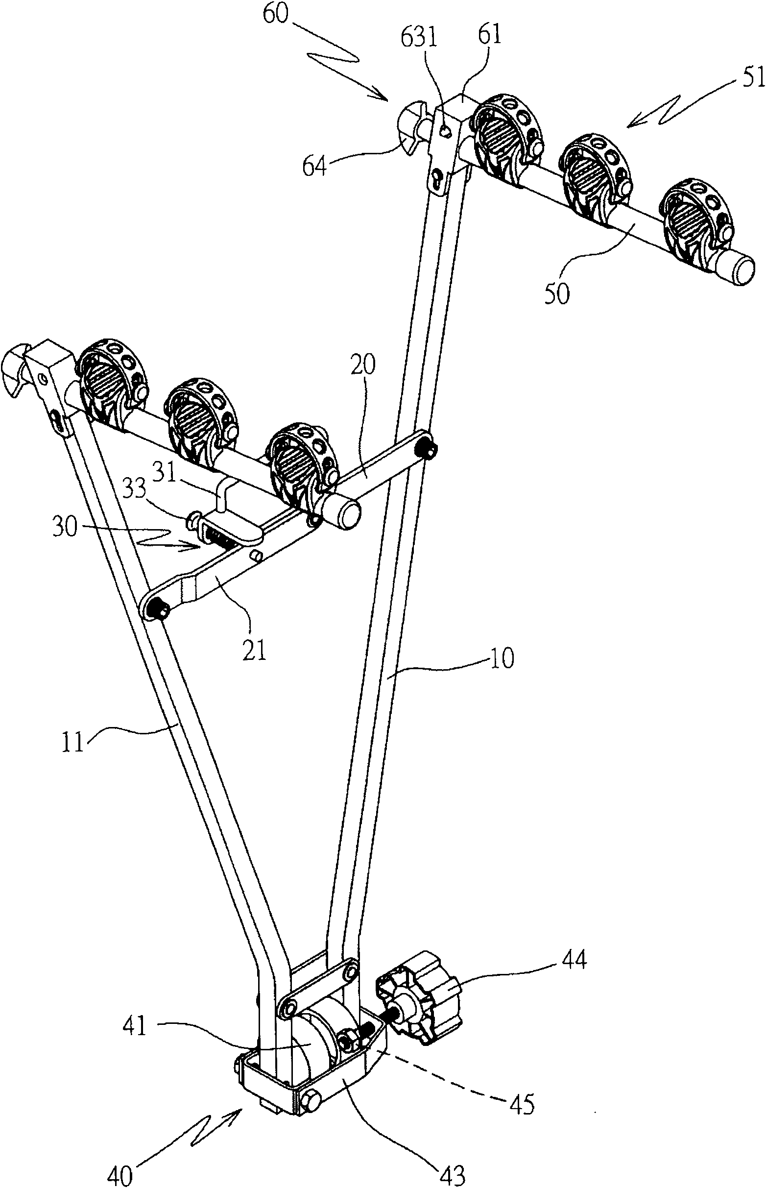
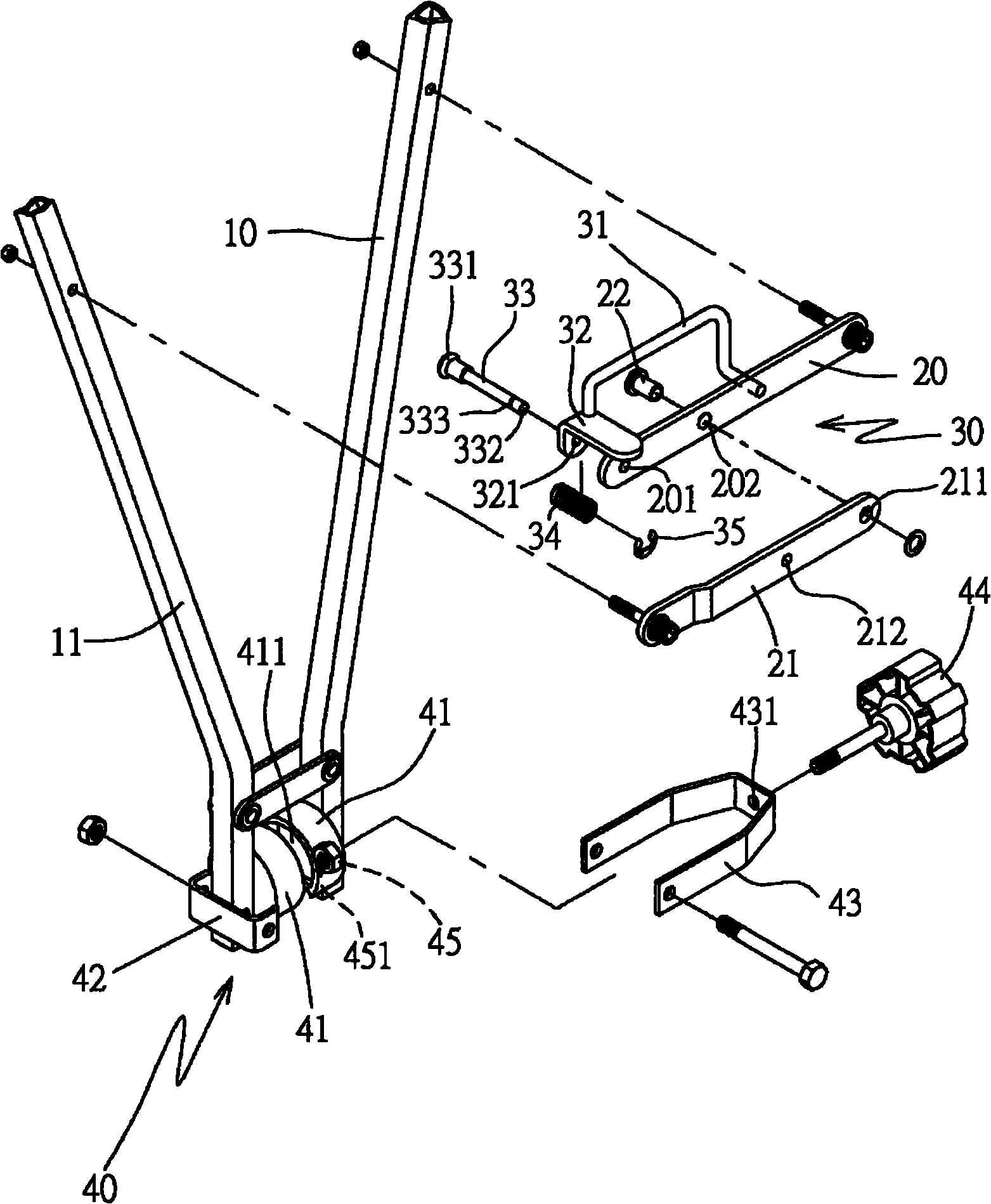
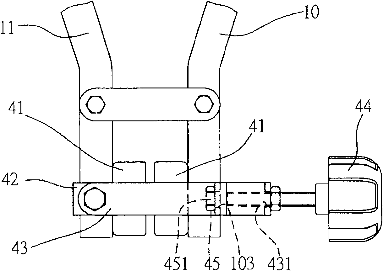
[0030] see Figures 1 to 4 The shown diagram of a preferred embodiment of the present invention is a frame structure and an anti-shake structure of the present invention, and its composition includes:

[0031] The two poles are first and second poles 10 and 11 having corresponding shapes, and the bottoms of the first and second poles 10 and 11 are pivotally connected to each other;

[0032]The two outer supports have first and second outer supports 20 and 21 pivotally connected to each other, which are assembled between the first and second support rods 10 and 11 and spread horizontally. ; wherein one end of the first outer support member 20 is pivotally connected to the appropriate position of the first pole 10, and the other end is respectively provided with first and second through holes 201, 202; One...


PUM


Abstract

The invention relates to a frame carrying structure comprising two supporting rods, two outer supporting pieces, an embedding piece, a clamping part and two crossbars. The bottoms of the first supporting rod and the second supporting rod are mutually connected; the outer supporting pieces, namely a first outer supporting piece and a second outer support piece are mutually pivoted, assembled between the supporting rods and horizontal strutted; the embedding part is assembled on the first outer supporting piece and the second outer supporting piece; the clamping part is assembled at the bottoms of the first supporting rod and the second supporting rod; the two crossbars are respectively assembled on the first supporting rod and the second supporting rod so that rod frames of the bicycle are erected on the two crossbars, wherein a connecting seat is mutually and pivotally connected with the crossbars; an elastic strutting sheet with a clamping end is assembled in each supporting rod; and the clamping ends can penetrate through the supporting rods and the connecting seat and can be separated from the connecting seat and the supporting rods through pressing the clamping ends of the elastic strutting sheets so that the crossbars can be in a braked, pivoted, stretched or folded action state, and convenient and practical efficacies can be provided for the whole structure.

Description

[0001] This case is a divisional application with the application number 200810184536.8, the application date is December 8, 2008, and the invention title is "carriage frame structure and anti-sway structure". technical field [0002] The invention relates to a frame structure and an anti-shake structure, especially a clamping part that can be firmly locked and positioned to prevent the frame from shaking. The rod produces an unfolding or folding action, providing a convenient and practical frame structure and anti-shake structure. Background technique [0003] With the improvement of the general public's awareness of leisure, many people often go out to engage in various leisure activities during holidays, so as to relax their bodies and minds. Among them, cycling activities are very popular among the public, and some users will set up a set at the rear of the vehicle. There is a frame structure capable of carrying bicycles, so that the bicycles can be transported to a remo...

Claims


Application Information

Patent Timeline
Patent Type & Authority Applications(China)
IPC IPC(8): B60R9/10B60R9/06
Inventor 王秋桂
Owner KING RACK INDUSTRIAL CO LTD
Why Eureka
Try Eureka