
Water tank structure of electric energy, solar energy or air energy water heater

A technology of air energy water heater and solar energy

Inactive Publication Date: 2011-08-10
刘运柳
View PDF1 Cites 59 Cited by
  • Summary
  • Abstract
  • Description
  • Claims
  • Application Information

AI Technical Summary

Problems solved by technology

[0002] Existing electric water heaters, solar energy, and air energy auxiliary heating all use ordinary stainless steel electric heating tubes to be completely immersed in water, and the water is charged and discharged when bathing; due to long use time, it will definitely break down and make the water electrified, causing more than 1,000 deaths and injuries in our country every year ;Patent application number 200910135082.X describes the structure of using light wave electric heating tubes. Previously, in the same water heater, only the same kind of electric heating tubes and the same heating method were used, so the scope of application was limited

Method used


Image

  • Water tank structure of electric energy, solar energy or air energy water heater
  • Water tank structure of electric energy, solar energy or air energy water heater
  • Water tank structure of electric energy, solar energy or air energy water heater

Examples


Embodiment Construction

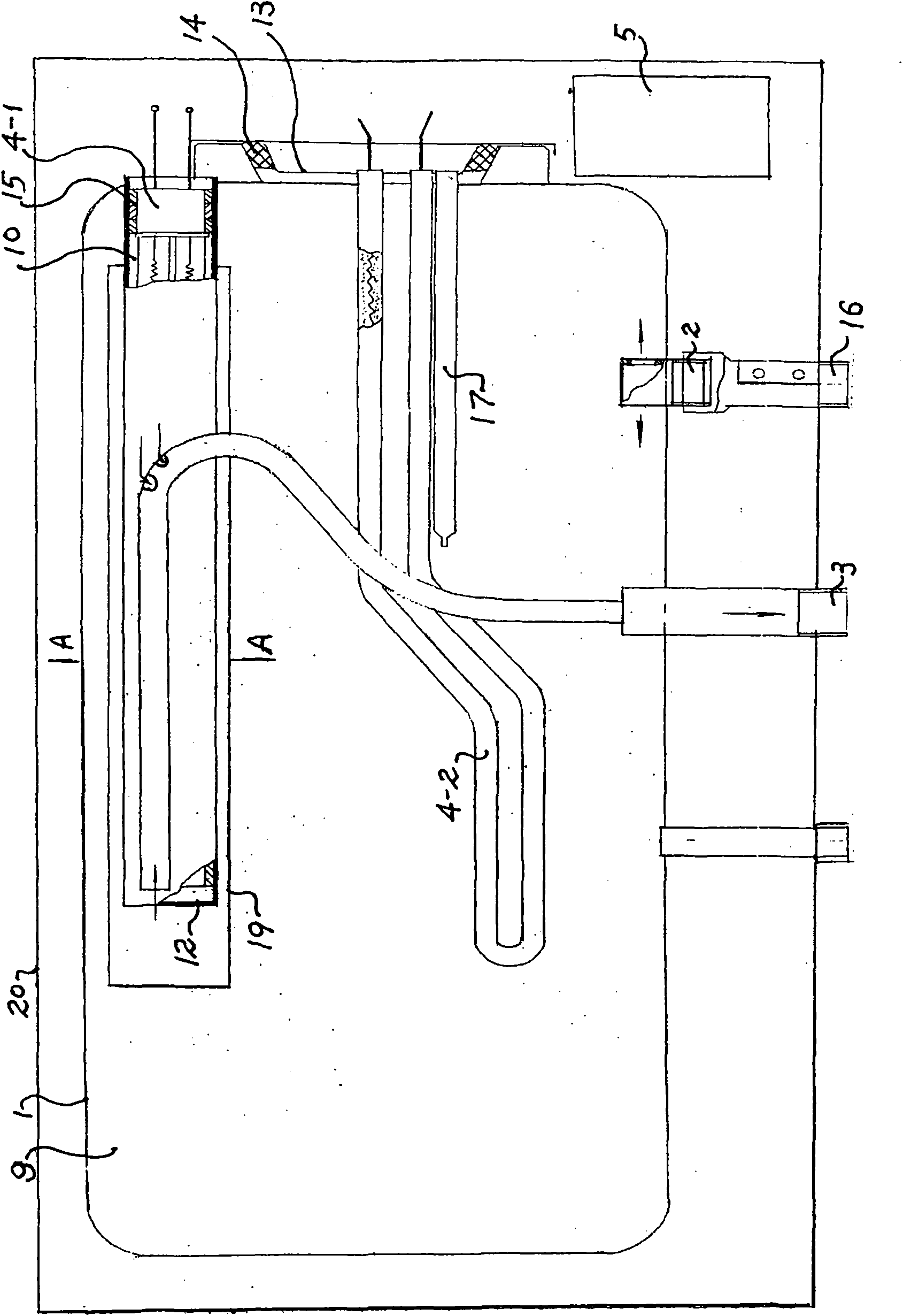
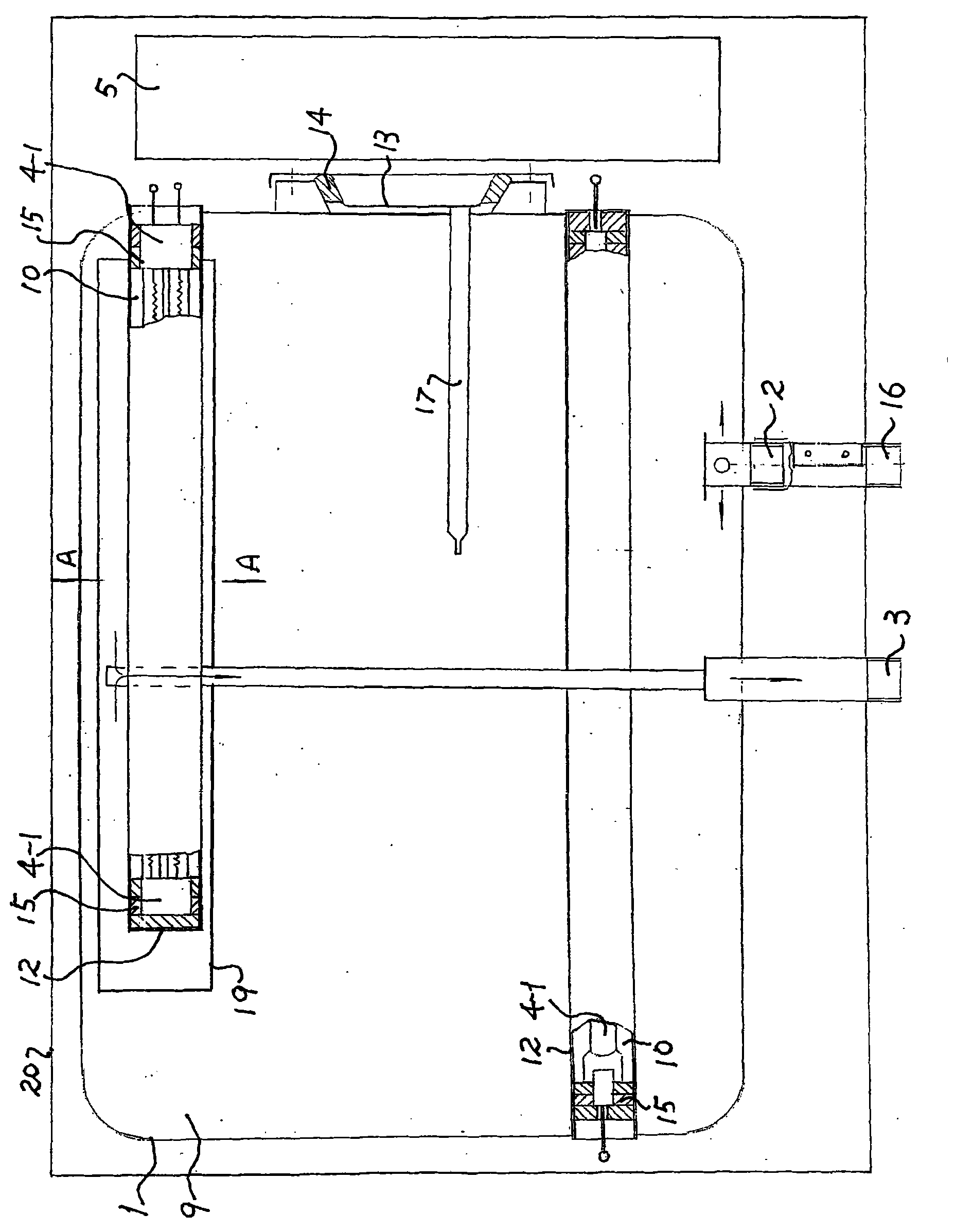
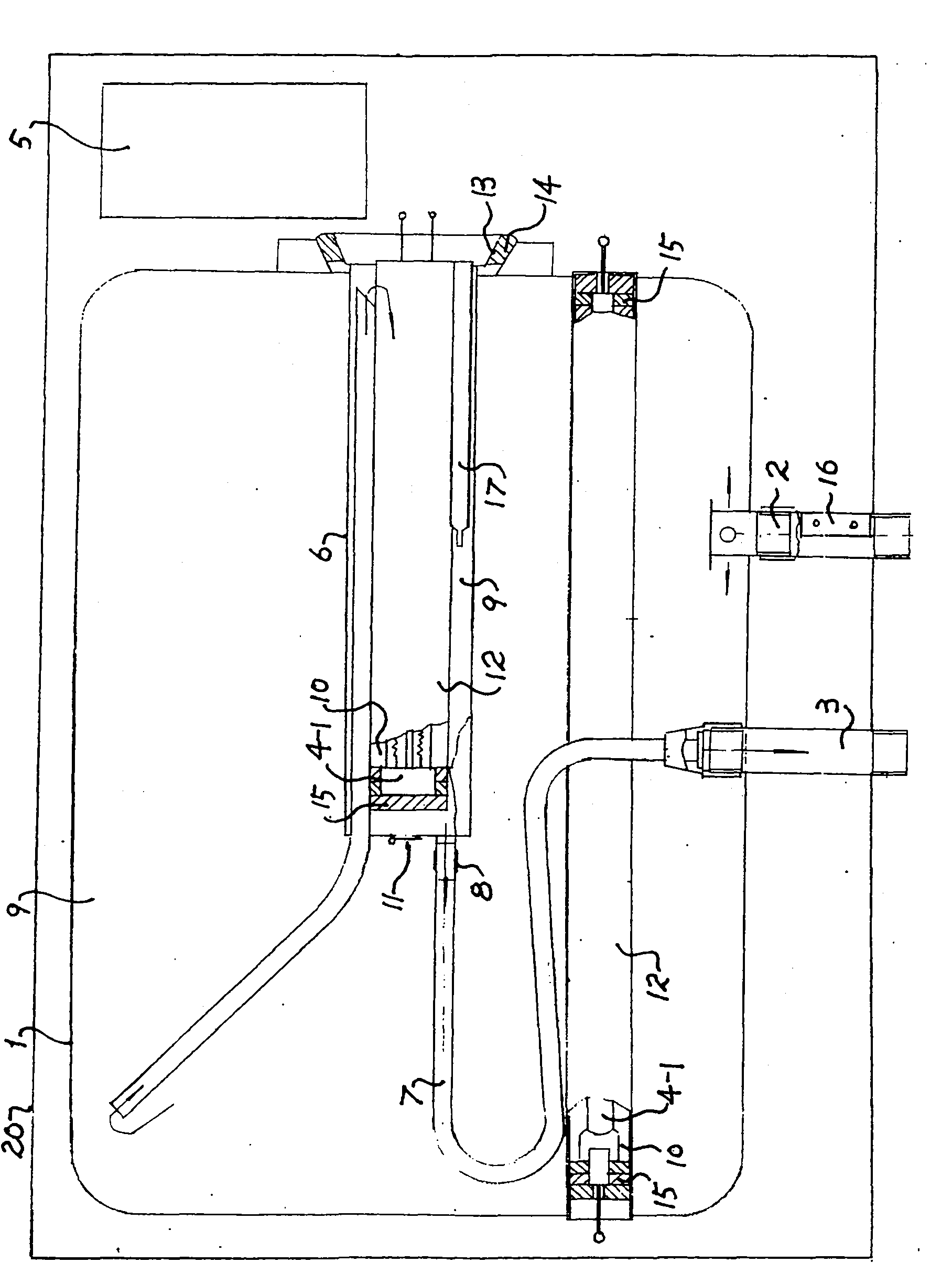
[0020] The following will be explained in conjunction with the accompanying drawings, which include: water tank 1, (cold water) water inlet 2, (hot water) water outlet 3, electric heating tube 4 (light wave fast heating or preheating electric heating tube 4-1, ordinary stainless steel electric heating tube Or silicon carbide tube 4-2), controller 5, heating water tank 6, connecting pipe 7, clamp 8, water 9, air 10, one-way valve 11, circular or wing-shaped metal or non- Metal tubular body 12, flange 13, sealing ring 14, electric heating tube insulation mounting pad 15, water flow sensor 16, temperature measuring tube 17, water mixing valve 18, energy gathering cover 19, shell 20

[0021] figure 1 It is a horizontal single-barrel electric water heater. Two types of electric heating tubes are installed in the water tank. The heating methods are different and the functions are also different; the upper part is equipped with a light wave electric heating tube 4-1, and the flange 1...


PUM


Abstract

The invention relates to a water tank structure of an electric energy, solar energy or air energy water heater, which comprises a water tank, electric heating tubes, an energy accumulating cover or heating water tank, a connecting tube and a check valve and is characterized in that more than one circular or wing-shaped metallic or nonmetallic tubular body (12) is installed on the water tank (1) or flange (13) in a firm welding or mechanical connection mode, wherein each of two ends or one end of each tubular body (12) is opened outwards, an optical wave electric heating tube (4-1) is arranged in each tubular body (12), and the water tank needs to be sealed; the optical wave electric heating tubes (4-1) generate heat radiation after being powered on, so that the metallic or nonmetallic tubular bodies (12) are heated, and the water surrounding the tubular bodies (12) is heated through the heat transfer of tube walls; and simultaneously, more than one common stainless steel electric heating tube or silicon carbide tube (4-2) is arranged in the water tank and does not work when the hot water is released. A section of a vacuum tube heat accumulator is inserted into the water tank of a solar energy water heater; a condenser or metallic tube heat exchanger is arranged in the water tank of an air energy water heater; and for each of the solar energy water heater and the air energy water heater, an electric auxiliary heating device is also arranged in the water tank, i.e. the upper part is provided with a rapid-heating electric heating tube, the lower part is provided with a preheating electric heating tube, the heating water tank can also be manufactured on the flange or other parts, a water pump is connected to an end part, and the check valve is installed at the water outlet of the water pump.

Description

technical field [0001] The invention relates to electric energy, solar energy and air energy water heaters, and mainly relates to the water tank structure of the water heater. Background technique [0002] Existing electric water heaters, solar energy, and air energy auxiliary heating all use ordinary stainless steel electric heating tubes to be completely immersed in water, and the water is charged and discharged when bathing; due to long use time, it will definitely break down and make the water electrified, causing more than 1,000 deaths and injuries in our country every year ; Patent Application No. 200910135082.X describes the structure of using light-wave electric heating tubes. Previously, in the same water heater, only the same electric heating tubes and the same heating method were used, and the scope of application was limited. Contents of the invention [0003] The present invention improves the above-mentioned structure. In the same water tank of electric energ...

Claims


Application Information

Patent Timeline
Patent Type & Authority Applications(China)
IPC IPC(8): F24H9/00F24H9/18F24J2/46
CPCY02E10/40
Inventor 刘运柳
Owner 刘运柳
Learn More