Hydraulic oil cylinder, hydraulic buffering system, excavator and concrete pump truck

A technology of hydraulic oil cylinder and buffer sleeve, applied in the field of hydraulic oil cylinder, can solve the problems of extremely high manufacturing precision requirements of buffer mechanism, hydraulic oil cylinder can not be used normally, and the manufacturing level is difficult to meet the requirements, so as to facilitate the organization of production, avoid mechanical failure, and process easy effect

Active Publication Date: 2012-07-18
SANY HEAVY IND CO LTD (CN)
View PDF0 Cites 0 Cited by
  • Summary
  • Abstract
  • Description
  • Claims
  • Application Information

AI Technical Summary

Problems solved by technology

At this time, the large buffer sleeve 04 in the above-mentioned buffer mechanism needs to be repeatedly inserted into the buffer inner hole 07 at high speed, and the fit gap between the two is originally very small, and the piston rod 03 is very heavy. It is easy to tilt to one side; therefore, the hydraulic cylinder used in the above occasions is prone to failure of the buffer mechanism that the buffer sleeve 04 cannot be inserted into the buffer inner hole 07, resulting in the failure of the entire hydraulic cylinder.
[0008] Another key problem of the above-mentioned buffer mechanism is that the outer diameter of the large buffer sleeve 04 must precisely match the inner diameter of the buffer inner hole 07, otherwise the buffer effect cannot be achieved; this results in extremely high manufacturing precision requirements for the buffer mechanism , the manufacturing level of general manufacturers is difficult to meet the requirements
Due to the above-mentioned high requirements for manufacturing precision, hydraulic cylinders with large strokes and large bores have become a bottleneck in the production of excavators and other construction machinery, which seriously limits the production capacity of various downstream manufacturers.

Method used


Image

  • Hydraulic oil cylinder, hydraulic buffering system, excavator and concrete pump truck
  • Hydraulic oil cylinder, hydraulic buffering system, excavator and concrete pump truck
  • Hydraulic oil cylinder, hydraulic buffering system, excavator and concrete pump truck

Examples


Embodiment Construction

[0064] In order to enable those skilled in the art to better understand the technical solution of the present invention, the present invention will be further described in detail below in conjunction with the accompanying drawings and specific embodiments.

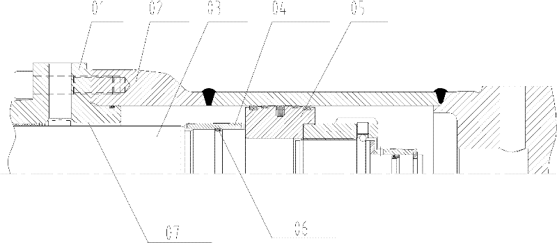
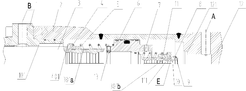
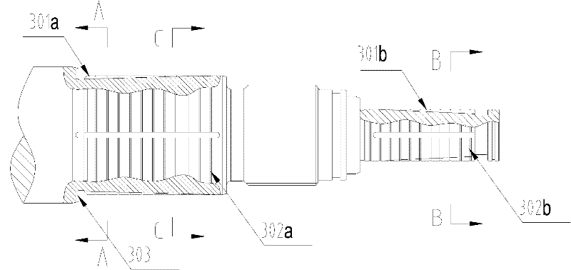
[0065] Please refer to Figure 2 to Figure 11 In the first specific embodiment, it includes a rod chamber end cover 1, a cylinder barrel 2, a piston rod 3, a piston 6 and a rodless chamber end cover 12, and the rod chamber end cover 1 is provided with a second oil passage B, The rodless chamber end cover 12 is provided with a first oil passage A, the piston rod 3 and the piston 6 divide the inner chamber of the hydraulic cylinder 2 into a rod chamber and a rodless chamber, the second oil passage B and the first oil passage Road A communicates with the oil passage of the hydraulic system, and is an axial oil passage provided on the hydraulic cylinder. The oil passage B includes the oil passage hole opened on the rod chambe...


PUM


Abstract

The invention discloses a hydraulic oil cylinder which comprises a rod cavity end closure, a cylinder barrel, a piston rod, a piston and a rodless cavity end closure, wherein the inner chamber of the hydraulic cylinder barrel is divided into a rod cavity and a rodless cavity by the piston rod and the piston; the piston rod is provided with a buffering sleeve which comprises a first buffering sleeve and / or a second buffering sleeve; the buffering sleeve can slide along the axial direction of the piston rod; an axial throttling oil passage is arranged between the buffering sleeve and the piston rod; the first buffering sleeve is provided with a sealing end surface; a sealing end surface is arranged on the rod cavity end closure; hydraulic oil in the rod cavity is discharged to an oil passage through the throttling oil passage; the end surface of the second buffering sleeve is in contact with the sealing end surface of the rodless cavity end closure to form a sealing; and the hydraulic oil in the rodless cavity is discharged to the oil passage through the throttling oil passage. The invention provides a buffering mechanism of the hydraulic oil cylinder; and the buffering mechanism has longer service life, has lower requirement on the accuracy of manufacturing and is convenient for organizing production.

Description

[0001] This application is a Chinese patent application submitted to the China Patent Office on July 23, 2010, with the application number 201010235138.1, and the title of the invention is "a hydraulic cylinder and its related devices, and hydraulic buffer system, excavator and concrete pump truck" (the A utility model patent application was submitted on the same day as the technical solution for which the application was requested to be protected, and relevant procedures were performed), and the divisional application was incorporated in its entirety by reference. technical field [0002] The invention relates to the field of hydraulic technology, in particular to a hydraulic oil cylinder. The invention also provides a hydraulic buffer system, an excavator and a concrete pump truck used for the hydraulic oil cylinder. Background technique [0003] The hydraulic cylinder is a widely used part in construction machinery. During its working process, the piston needs to reciproc...

Claims


Application Information

Patent Timeline
Patent Type & Authority Patents(China)
IPC IPC(8): F15B15/14F15B15/20F15B15/22
Inventor 易小刚刘永东陈兵兵
Owner SANY HEAVY IND CO LTD (CN)
Why Eureka
Try Eureka