Spindle drive

A technology of main shaft transmission and transmission device, applied in transmission device, gear transmission device, transportation and packaging, etc., can solve the problem of high cost of main shaft nut

Active Publication Date: 2011-08-17
BROSE FAHRZEUGTEILE GMBH & CO KG
View PDF3 Cites 7 Cited by
  • Summary
  • Abstract
  • Description
  • Claims
  • Application Information

AI Technical Summary

Problems solved by technology

[0005] The external teeth are thus formed by radially inward recesses in the outer cylindrical housing surface of the spindle nut, where the spindle nut known from WO 2005/015054 A1 is laterally passed through a toothless, For example, for the demarcation of the ...

Method used


Image

  • Spindle drive
  • Spindle drive
  • Spindle drive

Examples


Embodiment Construction

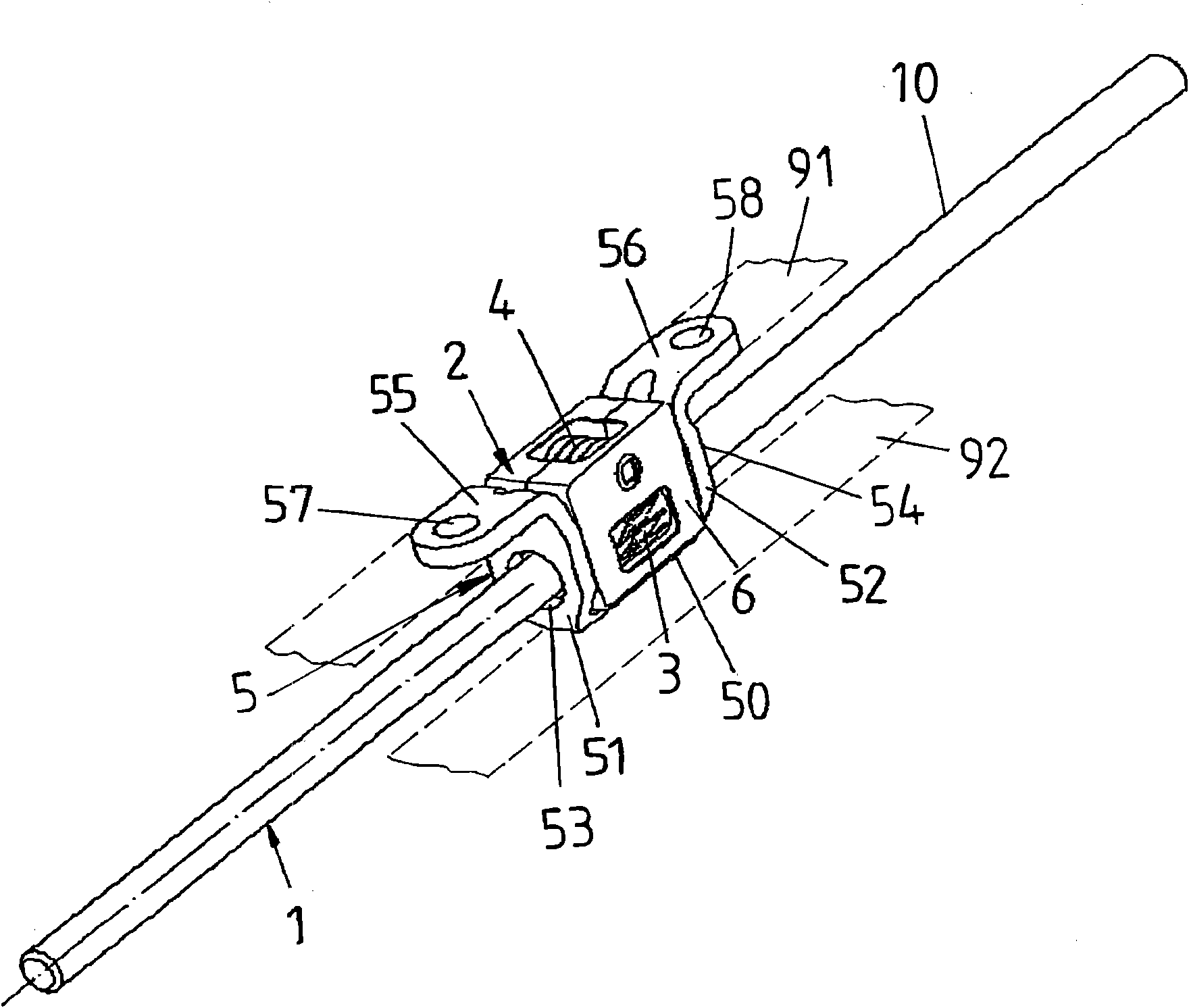
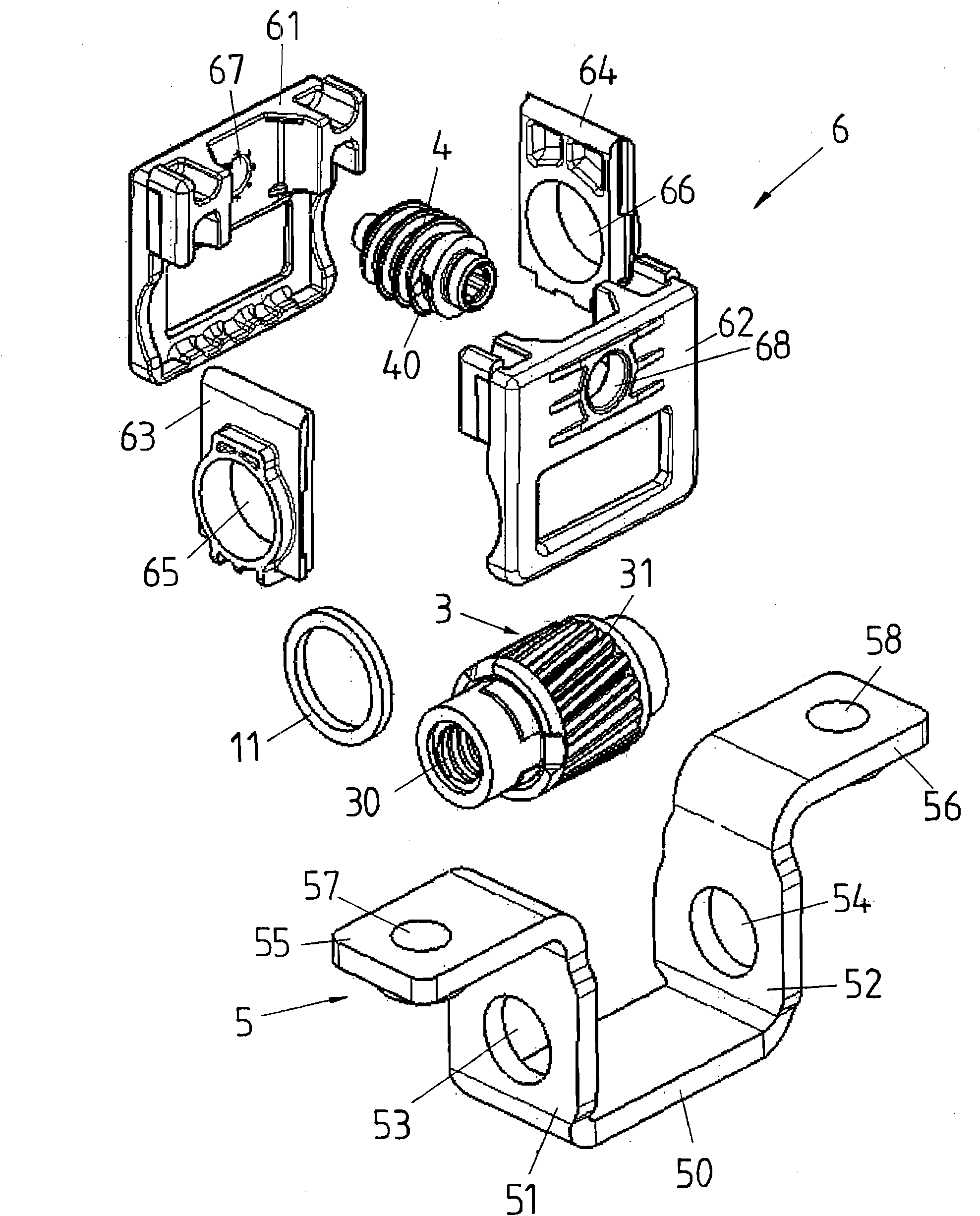
[0056] one in figure 1 The spindle drive shown in has a spindle 1 arranged (only schematically) on a fixed rail 92 of the body, which engages with an adjusting drive 2 which is connected to a (schematically shown) for the vehicle seat Shown) the adjustment rail 91 of the seat longitudinal adjustment device is connected, for example, the upper rail that is slidably installed on the fixed (lower) rail 92 of the vehicle body. The retaining angle 5 is used to fasten the adjusting gear 2 on the adjusting rail 91 and is preferably made of metal and in particular steel, it has a base body 50 and two side legs 51 , 52 in Through-holes 53 , 54 for the spindle 1 are provided in each case. From the two side legs 51, 52 of the holding angle 5 protrude respectively a fastening flange 55, 56, said fastening flange has fastening points 57, 58 in the form of fastening holes, by means of which fastening points the holding angle 5 is fixed on On the adjustment rail, the adjustment gear 2 is a...


PUM


Abstract

The invention relates to a spindle drive which has a spindle extending in longitudinal direction, a driving worm of an adjusting drive, and a spindle nut of the adjusting drive, which is in engagement with the spindle over an internal tooth and with the driving worm over an external tooth such that the spindle nut is displaceable into a rotary motion by the driving worm to adjust the adjusting drive along the spindle. The external tooth extends with a tooth depth (H) from a first end surface (33) along a cylindrical housing surface (32) towards a second end surface (34). In such a structure, the spindle drive satisfies rigid requirements for a spindle drive and the spindle nut can be simply produced especially by plastic injection moulding.

Description

technical field [0001] The invention relates to a main shaft transmission device. Background technique [0002] Spindle drives of this type are used, for example, in vehicles as adjustment devices for adjusting two vehicle components relative to one another, for example for longitudinal adjustment of vehicle seats. Such a spindle drive has a longitudinally extending spindle and an adjusting drive arranged on the spindle with a spindle nut and a drive worm. In this case, the spindle nut engages the spindle via internal teeth and the drive worm via external teeth in such a way that the drive of the drive worm can cause a rotational movement of the spindle nut in order to adjust the adjusting gear in the longitudinal direction along the spindle. . [0003] In the spindle nut of an adjusting gear known from WO 2005 / 015054 A1, the spindle nut is formed with at least one cylindrical middle section comprising an outer cylindrical housing surface and two end faces which adjoin the...

Claims


Application Information

Patent Timeline
IPC IPC(8): F16H1/16F16H25/20
CPCF16H55/22F16H25/20F16H55/0853B60N2/4214B60N2/067
Inventor 斯特凡·博泽克沃尔夫冈·苏克弗洛里安·利普安德烈娅·鲍尔扎克斯塞巴斯蒂安·艾克霍恩
Owner BROSE FAHRZEUGTEILE GMBH & CO KG
Why Eureka
Try Eureka