Moveable drawer with railing adjustment

A technology for adjusting mechanisms and movements, applied to drawers, furniture parts, household appliances, etc., to achieve the effect of improving the visual appearance

Active Publication Date: 2011-08-17
JULIUS BLUM GMBH
View PDF11 Cites 10 Cited by
  • Summary
  • Abstract
  • Description
  • Claims
  • Application Information

AI Technical Summary

Problems solved by technology

The disadvantage here is that the threaded element is only suspended from the panel and can only be connected relatively firmly to the panel via a retracted sleeve

Method used


Image

  • Moveable drawer with railing adjustment
  • Moveable drawer with railing adjustment
  • Moveable drawer with railing adjustment

Examples


Embodiment Construction

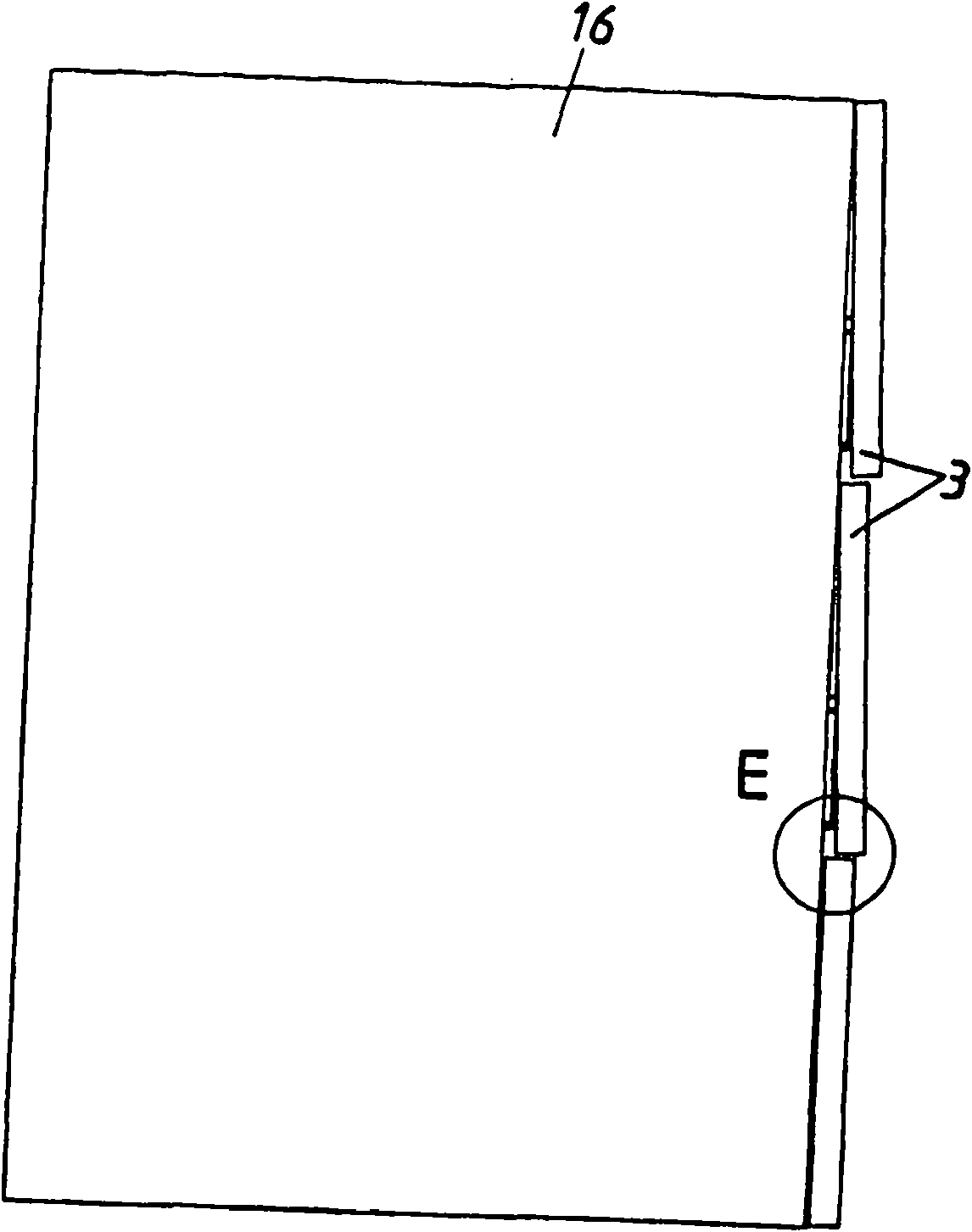
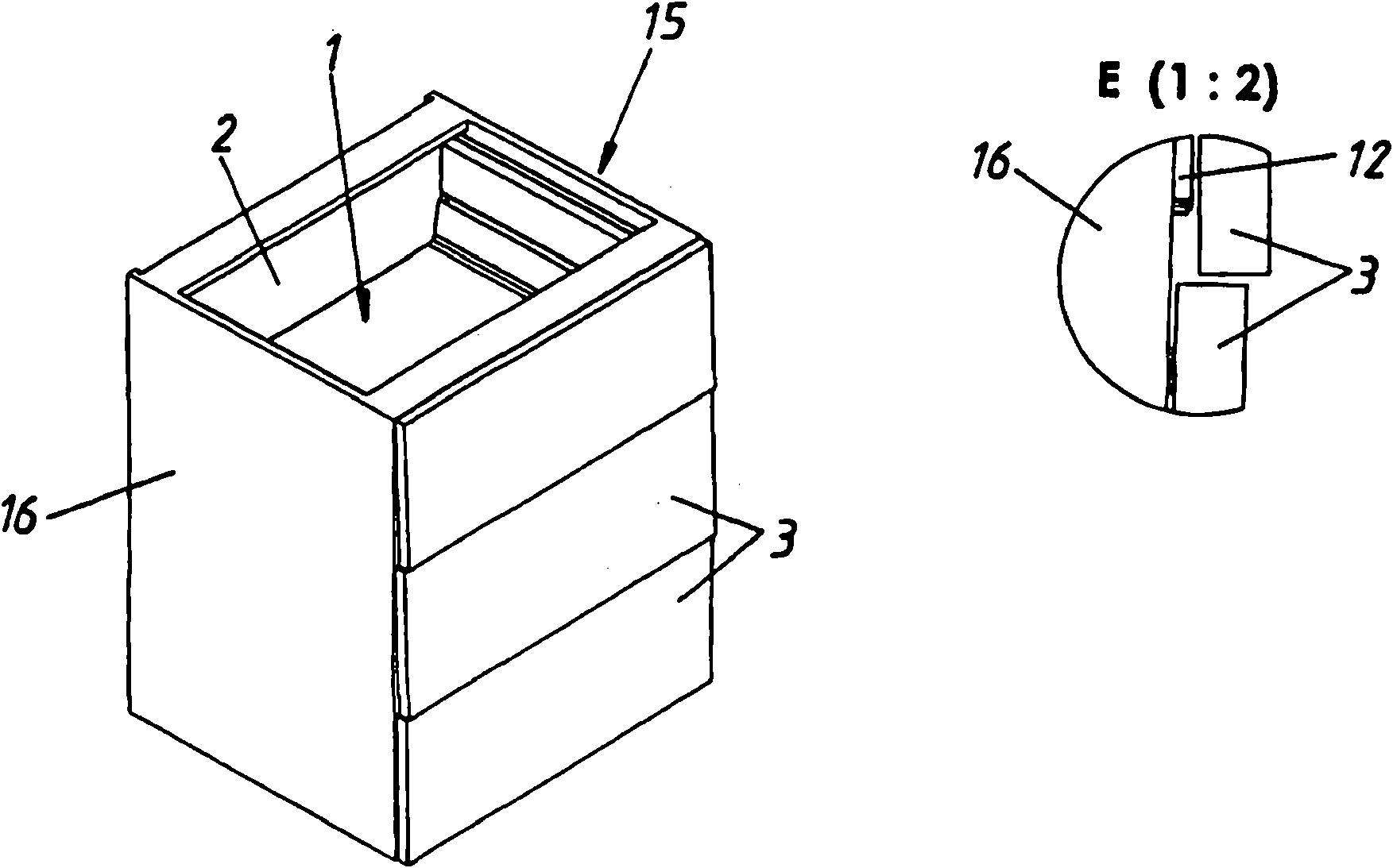
[0025] figure 1 with 2 A piece of furniture 15 is shown in , in which three drawers 1 are guided in a furniture body 16 shown therein. The inclination of the two panels 3 , which are inclined with respect to the orientation of the frame 12 and the furniture body 16 , can be seen in detail E. This leads to a scaly appearance of the panel 3 of the furniture 15 . This inclination is achieved or can also be compensated for by the adjusting mechanism according to the invention.

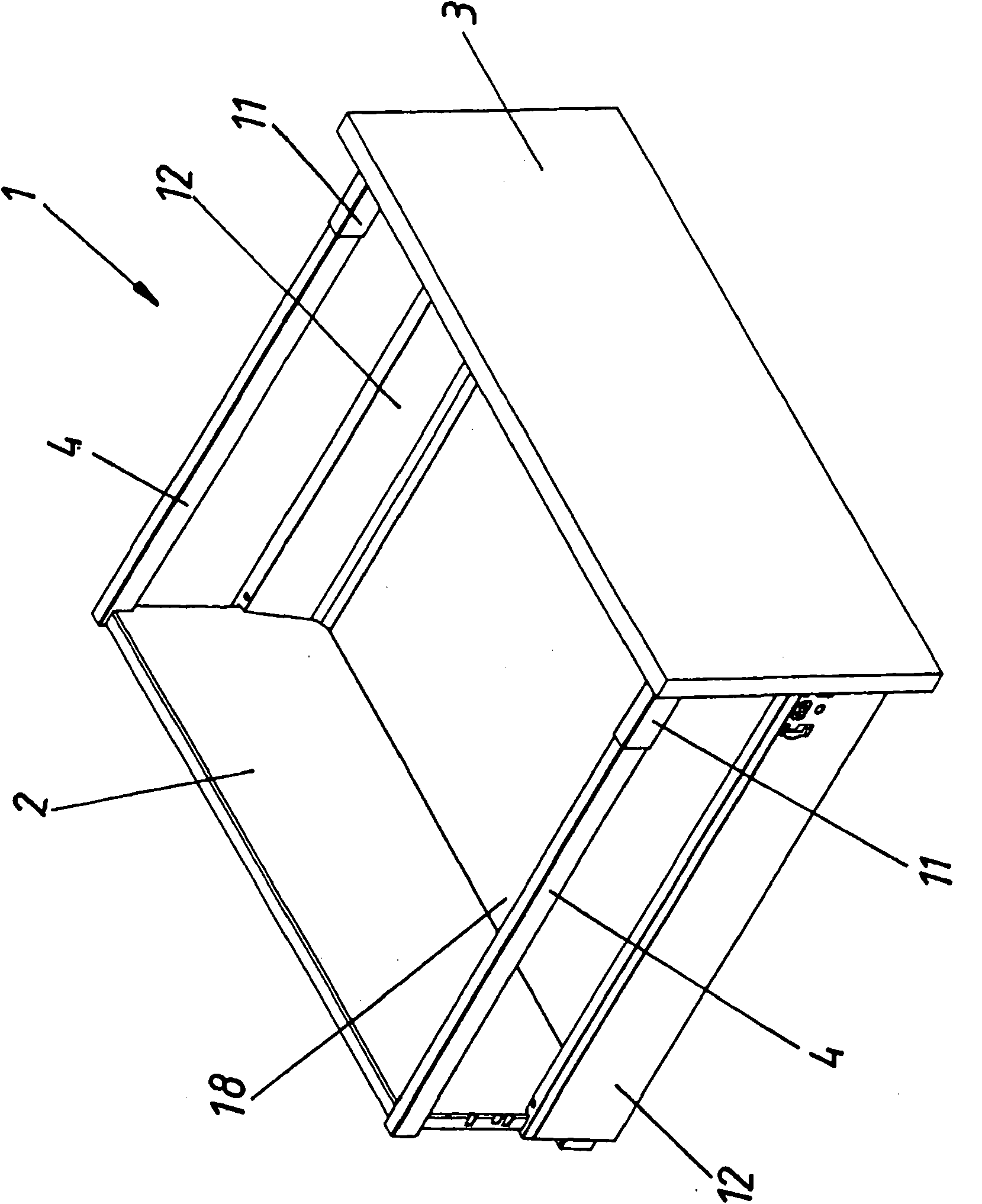
[0026] image 3 A movable furniture part or drawer 1 is shown in , which is formed at least from a rear wall 2 , a front panel 3 , a drawer frame 12 with a drawer bottom 18 , and two railing parts 4 with a cover 11 .

[0027] Figure 4 A railing assembly 19 is shown in , wherein the railing bar 4 , the cover 11 , the panel fixing element 7 and the snap-fit ​​connection element 10 can be seen.

[0028] Figure 5 The railing assembly 19 is shown in an exploded view, in which it can be seen that an ad...


PUM


Abstract

The present invention relates to moveable furniture part (1), in particular a drawer, with a railing rod (4) arranged between a back wall (2) and a front aperture (3), wherein the railing rod (4) is attached via a pivoting adjustment element (5) to the front aperture and by turning of the adjusting element (5), the front aperture (3) is inclined, characterized in that upon turning of the adjusting element (5), both the distance (X) of the adjusting element (5) to the front aperture (3) and also to the railing rod (4) is changed.

Description

technical field [0001] The invention relates to a movable furniture part, in particular a drawer, which has a railing member arranged between the rear wall and the panel, wherein the railing member is mounted on the panel by a rotatable adjustment mechanism, by The rotation of the adjustment mechanism causes the panel to tilt. Background technique [0002] Such movable furniture parts or drawers are known and are mainly used for adapting and adjusting the fronts of one or more drawers arranged one or more above or side by side in one or more furniture bodies. The adjustment is mainly carried out during the installation of the furniture, so that the alignment lines of the furniture fronts are configured as uniformly as possible and meet aesthetic requirements. [0003] Documents DE 90 01 486 U1, DE 195 07 322 U1 and DE 198 30 740 A1 known from the prior art relate to furniture pull-outs with panels which are connected to the railing via a rotatable (threaded) ) the adjustin...

Claims


Application Information

Patent Timeline
Patent Type & Authority Applications(China)
IPC IPC(8): A47B88/00
CPCA47B88/0055A47B88/0085A47B88/931A47B88/956
Inventor F·哈特尔
Owner JULIUS BLUM GMBH
Why Eureka
Try Eureka