
Solid-state lamps with improved radial emission and thermal performance

a technology of solid-state lamps and thermal performance, which is applied in the direction of point-like light sources, spectral modifiers, lighting and heating apparatus, etc., can solve the problems of inefficiency of traditional incandescent light bulbs, life time problems, and the difficulty of known led-based lamps matching the functionality and form factor of incandescent bulbs, so as to achieve improved emission and thermal characteristics

Inactive Publication Date: 2013-07-11
INTEMATIX
View PDF13 Cites 10 Cited by
  • Summary
  • Abstract
  • Description
  • Claims
  • Application Information

AI Technical Summary

Benefits of technology

The invention is a lamp with a solid-state light emitting device, thermally conductive body, duct, and photoluminescence wavelength conversion component. The duct cools the body and light emitting device through thermal airflow, and the photoluminescence wavelength conversion component is designed to improve the appearance of the off-state. The lamp can also have a light diffusive component that encloses the light emitting device. The technical effects of this invention are improved cooling and better visual appearance of the lamp.

Problems solved by technology

Traditional incandescent light bulbs are inefficient and have life time issues.
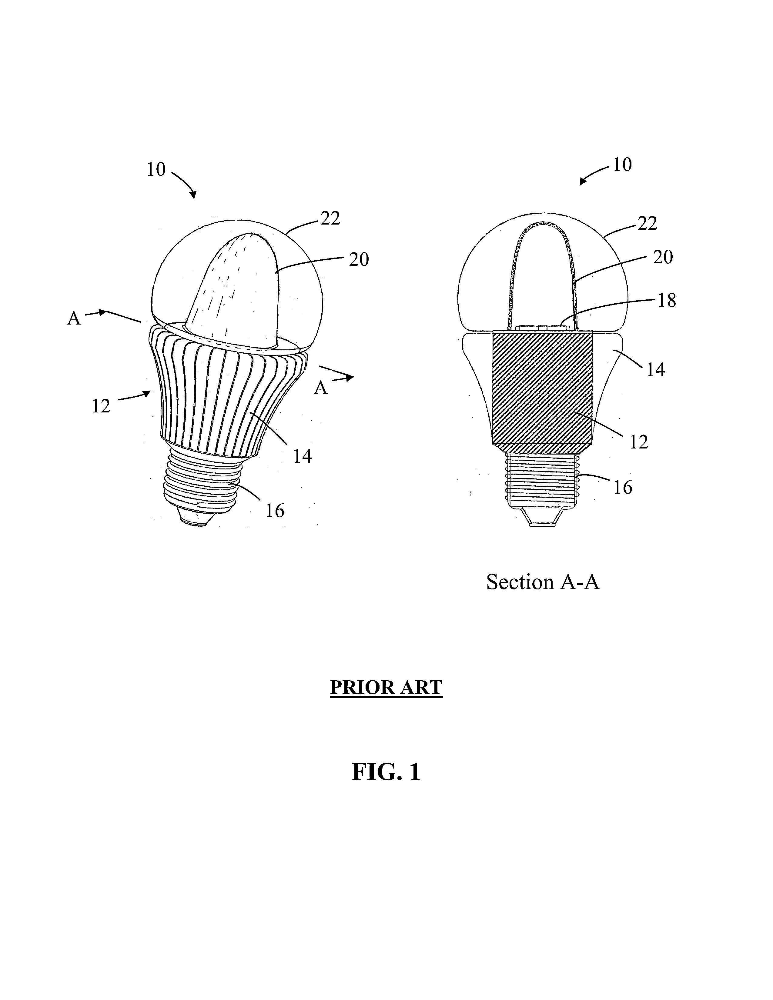
However the known LED-based lamps typically have difficulty matching the functionality and form factor of incandescent bulbs.

Method used


Image

  • Solid-state lamps with improved radial emission and thermal performance
  • Solid-state lamps with improved radial emission and thermal performance
  • Solid-state lamps with improved radial emission and thermal performance

Examples


Embodiment Construction

[0066]Throughout this patent specification like reference numerals are used to denote like parts.

[0067]Lamps (light bulbs) are available in a number of forms, and are often standardly referenced by a combination of letters and numbers. The letter designation of a lamp typically refers to the particular shape of type of that lamp, such as General Service (A, mushroom), High Wattage General Service (PS—pear shaped), Decorative (B—candle, CA—twisted candle, BA—bent-tip candle, F—flame, P—fancy round, G—globe), Reflector (R), Parabolic aluminized reflector (PAR) and Multifaceted reflector (MR). The number designation refers to the size of a lamp, often by indicating the diameter of a lamp in units of eighths of an inch. Thus, an A-19 type lamp refers to a general service lamp (bulb) whose shape is referred to by the letter “A” and has a maximum diameter two and three eights of an inch. As of the time of filing of this patent document, the most commonly used household “light bulb” is the...


PUM


Abstract

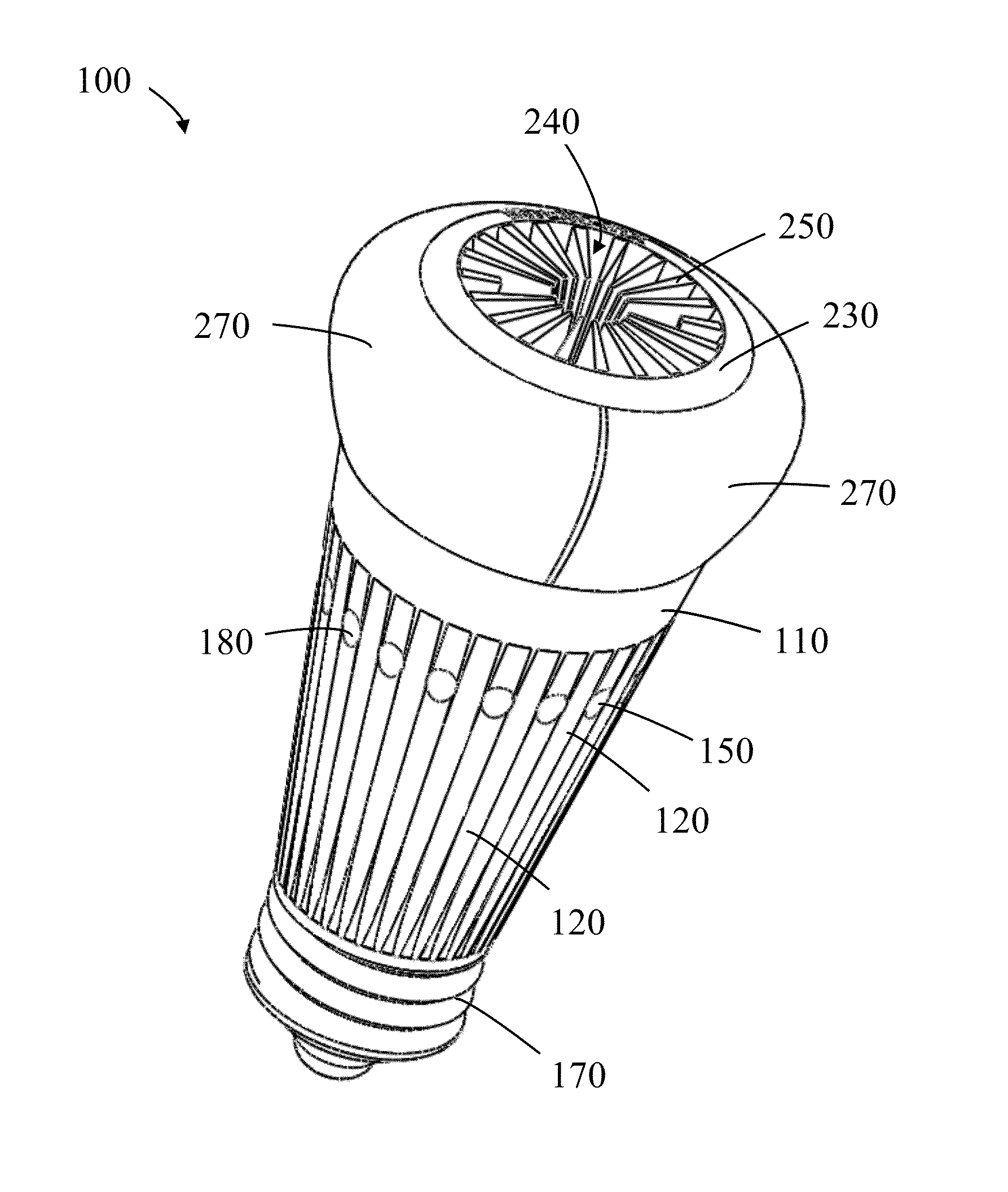
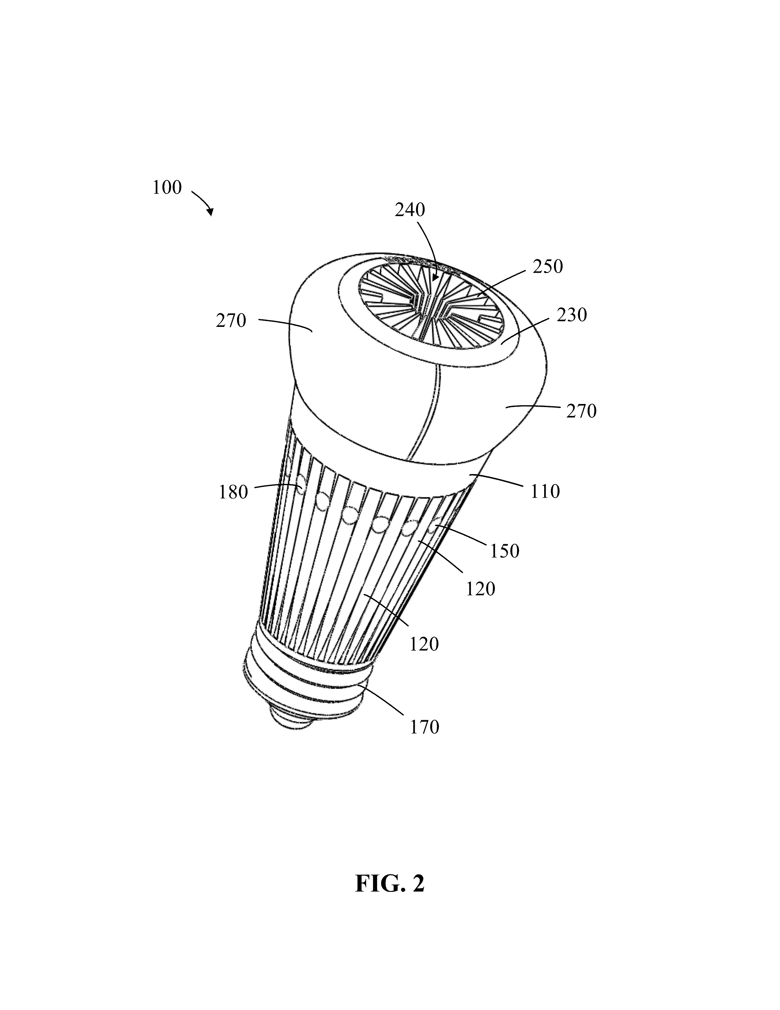
A solid-state lamp is described that includes a first light emission zone and a second light emission zone, where the first light emission zone is longitudinally spaced apart from the second light emission zone. The light emission zones comprise a photoluminescence wavelength conversion component and a solid state light emitting device. The lamp comprises a lower body, a central body, and an upper duct, where the central body, and the upper duct together define at least one passageway / duct for thermal airflow.

Description

CROSS-REFERENCES TO RELATED APPLICATIONS[0001]This application claims priority to the following:[0002]a) benefit of priority to U.S. Provisional Application No. 61 / 644,427 filed on May 8, 2012;[0003]b) benefit of priority to U.S. Provisional Application No. 61 / 544,272 filed on Oct. 6, 2011;[0004]c) benefit of priority to U.S. Provisional Application No. 61 / 568,138 filed on Dec. 7, 2011;[0005]d) is a continuation-in-part of U.S. application Ser. No. 13 / 411,497 filed on Mar. 2, 2012, which claims the benefit of priority to U.S. Provisional Application No. 61 / 544,272 filed on Oct. 6, 2011 and to U.S. Provisional Application No. 61 / 568,138 filed on Dec. 7, 2011;[0006]e) is a continuation-in-part of U.S. application Ser. No. 13 / 451,470 filed on Apr. 19, 2012, which is a continuation of U.S. application Ser. No. 13 / 411,497 filed on Mar. 2, 2012, which claims the benefit of priority to U.S. Provisional Application No. 61 / 544,272 filed on Oct. 6, 2011 and to U.S. Provisional Application No....

Claims


Application Information

Patent Timeline
Patent Type & Authority Applications(United States)
IPC IPC(8): F21V29/00F21V9/16
CPCF21V13/02F21V29/2293F21V9/16F21K9/13F21K9/1355F21V29/83F21V3/02F21Y2101/02F21V29/713F21V29/773F21K9/56F21K9/23F21K9/64F21Y2115/10F21V13/08
Inventor YANG, HAITAOLEE, HYUNG-CHULEDWARDS, CHARLESLI, YI-QUN
Owner INTEMATIX
Learn More