
Selecting a reference image for images to be joined

a reference image and image processing technology, applied in the field of image processing techniques and tools, can solve the problems of object depicted in two different images having the same size, less field of view, etc., and achieve the effect of improving the overall appearance of the joined images, reducing the distortion of the remaining images, and improving the visual appearance of the composite imag

Active Publication Date: 2011-08-09
ADOBE SYST INC
View PDF14 Cites 11 Cited by
  • Summary
  • Abstract
  • Description
  • Claims
  • Application Information

AI Technical Summary

Benefits of technology

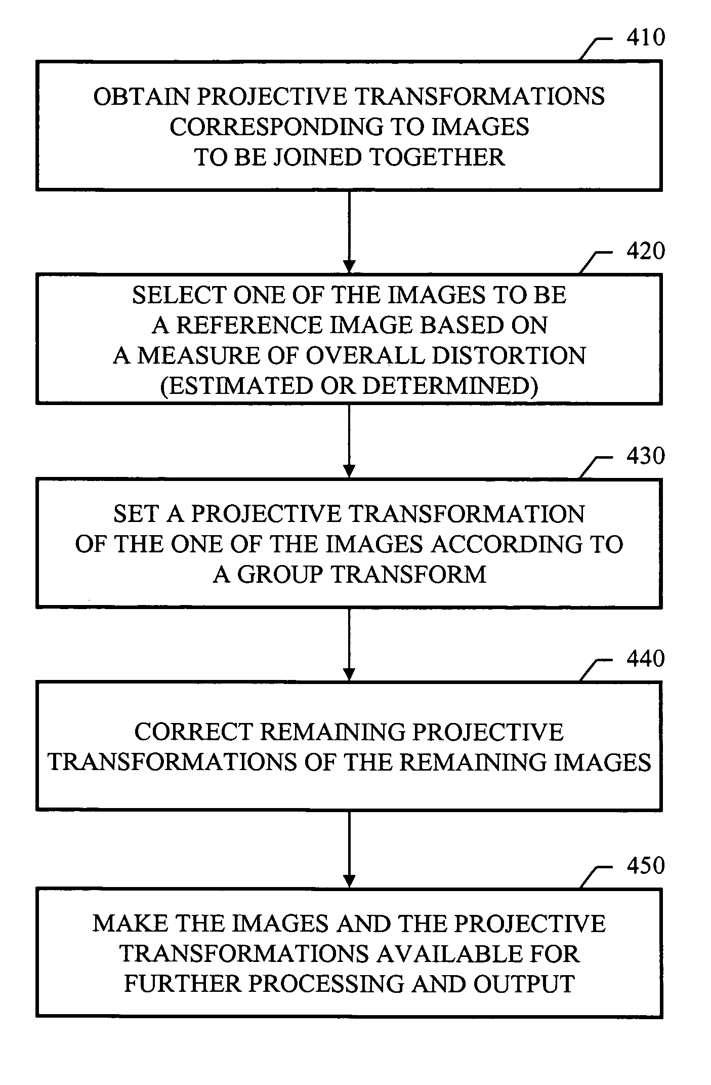
Particular embodiments of the subject matter described in this specification can be implemented to realize one or more of the following advantages. A visually pleasant layout for a set of images stitched together under projective transformations can be automatically computed, while at the same time, user input can be respected, and a warning can be provided to the user their choices are not ideal. The warning can be provided before the images are actually distorted based on a user's selected reference image, which can avoid potential problems that may arise when applying an inappropriate choice of reference image (e.g., when a selected reference image causes other images to be distorted so much that something drastic happens, such as running out of memory space when applying a projective transformation).
The visually pleasant layout can be determined by finding the image that, when fixed as a non-transformed reference image, minimizes the distortion of the remaining images, in accordance with projective transformations generated by automatic image alignment software. Forcing one of the images to be a reference image, which is not transformed (separate from any universal transform for the set of images), can result in an improved visual appearance for the composite image since one of the images in the set to be joined is often the most interesting one, and keeping such an image undistorted can improve the overall appearance of the joined images.
The user experience of image stitching can be enhanced. The user can be free to explicitly specify a reference image. However, if the user does not specify a reference image, an appropriate image in the set can automatically be chosen as the reference image. Moreover, when the user does specify a reference image, the resulting composition under this choice can be automatically checked to see if it causes large distortion for other images in the set. If the distortions are large, the user can be warned, and the automatically computed reference image can be suggested as an alternative reference image.

Problems solved by technology

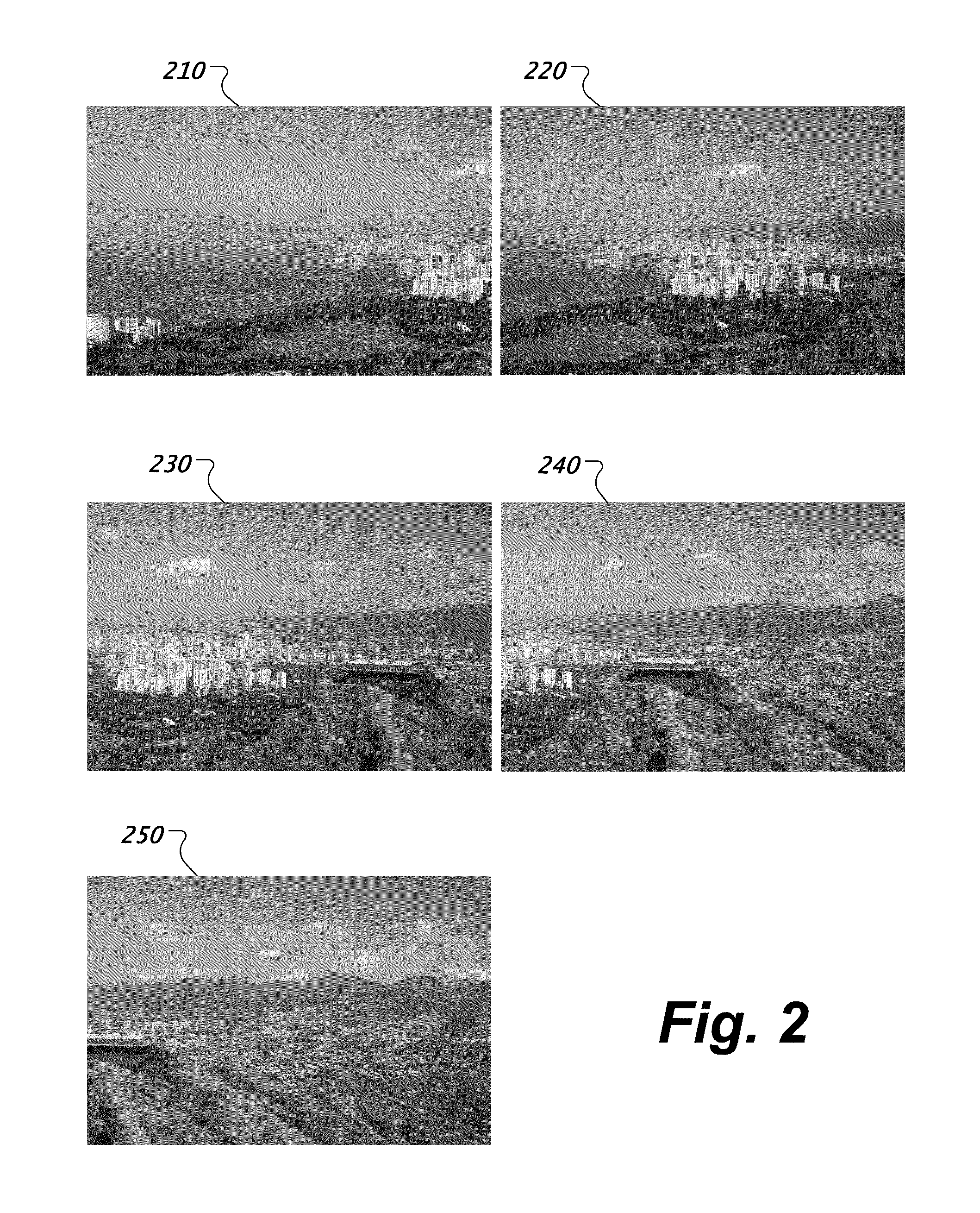
Image capture devices, such as cameras, can be used to capture an image of a section of some larger view, and such image capture devices can have a field of view that is less than desired.
Consequently, an object depicted in two different images might not have the same size in the two images, because of perspective distortion.

Method used


Image

  • Selecting a reference image for images to be joined
  • Selecting a reference image for images to be joined
  • Selecting a reference image for images to be joined

Examples


Embodiment Construction

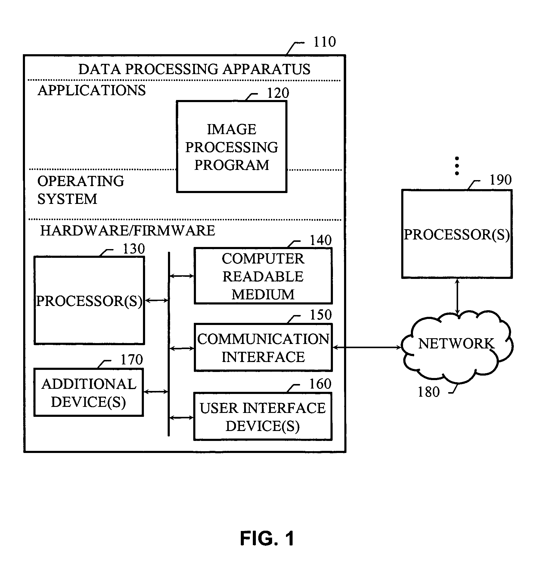
FIG. 1 shows an example system programmed to select a reference image, for images to be joined together in accordance with projective transformations, based on a measure of overall distortion for the images. A data processing apparatus 110 can include hardware / firmware, an operating system and one or more programs, including image processing program 120. The image processing program 120 operates, in conjunction with the data processing apparatus 110, to effect various operations described in this specification. Thus, the program 120, in combination with processor(s) and computer-readable media (e.g., memory), represents one or more structural components in the system.

The image processing program 120 can be an image processing application, or a portion thereof. As used herein, an application refers to a computer program that the user perceives as a distinct computer tool used for a defined purpose. An application can be built entirely into the operating system (OS) of the data proces...


PUM


Abstract

The present disclosure includes systems and techniques relating to selecting a reference image for images to be joined in accordance with projective transformations. In general, one aspect of the subject matter described in this specification can be embodied in a computer-implemented method that includes obtaining projective transformations corresponding to two dimensional images to be joined together in accordance with the projective transformations; selecting one of the two dimensional images to be a reference image for remaining ones of the two dimensional images, the selecting being based on a measure of overall distortion for the two dimensional images; setting a projective transformation of the one of the images according to a group transform; correcting remaining projective transformations of the remaining images in accordance with the setting the projective transformation of the one of the images; and making the two dimensional images and the projective transformations available for further processing and output.

Description

BACKGROUNDThe present disclosure relates to image processing techniques and tools for stitching together two dimensional images.Image capture devices, such as cameras, can be used to capture an image of a section of some larger view, and such image capture devices can have a field of view that is less than desired. Thus, to generate an image of the larger view, multiple overlapping images of sections of the view can be taken, and the images can be stitched together to form a composite image, which may sometimes be referred to as a panoramic image. An image captured by a camera often distorts the sizes of objects depicted in the image so that distant objects appear smaller than closet objects. The size distortion, which is known as perspective distortion, depends on the camera position, the pointing angle of the camera, and so forth. Consequently, an object depicted in two different images might not have the same size in the two images, because of perspective distortion.Different ima...

Claims


Application Information

Patent Timeline
Patent Type & Authority Patents(United States)
IPC IPC(8): G06K9/36G06K9/00G09G5/00
CPCG06T3/4038
Inventor JIN, HAILINCHIEN, JEN-CHAN
Owner ADOBE SYST INC
Learn More