
Radial shaft seal for separating two media

A sealing device and radial shaft technology, applied in the direction of engine sealing, engine components, mechanical equipment, etc., can solve the need for front and rear sequential connections, cannot provide axial structural length, and seal ring assembly cannot be carried out separately in succession, etc. question

Inactive Publication Date: 2011-08-24
CARL FREUDENBERG KG
View PDF12 Cites 7 Cited by
  • Summary
  • Abstract
  • Description
  • Claims
  • Application Information

AI Technical Summary

Problems solved by technology

However, the connection of two identically designed shaft sealing rings one behind the other requires a large axial construction length, which in many cases cannot be provided
Furthermore, the assembly of the sealing rings cannot be carried out sequentially and separately

Method used


Image

  • Radial shaft seal for separating two media
  • Radial shaft seal for separating two media
  • Radial shaft seal for separating two media

Examples


Embodiment Construction

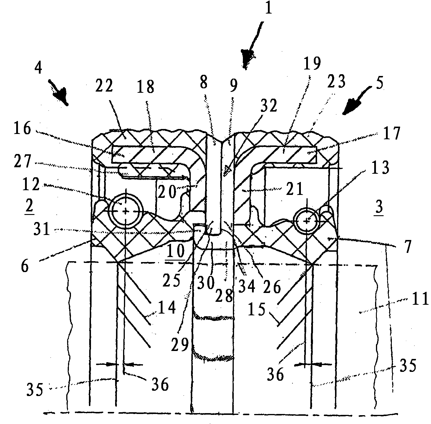
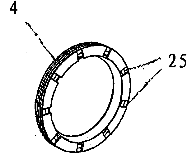
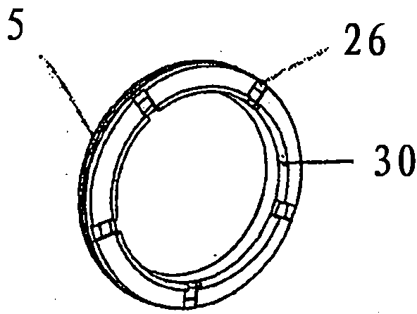
[0014] exist figure 1 The embodiment of a radial shaft seal 1 shown in for separating two media in spaces 2 and 3 not shown in detail basically comprises radial shaft seal rings 4 and 5 which The seals are connected to each other in a ring-locking manner. The sealing lips 6 and 7 are oriented axially opposite. Their bases 8 and 9 bear against each other in the assembled state. The space 10 formed between the sealing lips 6 and 7 is provided with an outward ventilation 32 . The shaft 11 surrounded by the seal is shown in dashed lines. The sealing lip 6 visible in the figure is larger than the sealing lip 7 . In this embodiment, the coil springs 12 and 13 used have different dimensions and are matched accordingly. Also possible are embodiments in which the two lips are of the same size. The sealing lips 6 and 7 are each provided with return grooves 14 and 15 , which bring about a return of leakage fluid in the corresponding direction of rotation of the shaft. In this case...


PUM


Abstract

A radial shaft seal for separating two media includes two radial shaft sealing rings each including an axial surface and a sealing lip. The sealing rings are disposed with the axial surfaces facing one another and the sealing lips axially opposed to one another with a space between the sealing lips including a vent. At least one of the sealing rings includes clamping cams configured to grip an inner rim of the other sealing ring so as to join the sealing rings in a form-locking, rear-engaging position relative to each other.

Description

technical field [0001] The invention relates to a radial shaft seal for separating two media, comprising two radial shaft seal rings connected to each other in a form-locking manner, the two radial shaft seal rings face each other with their bottom faces, and Their sealing lips are positioned axially opposite each other, wherein the space between these sealing lips is provided with ventilation. Background technique [0002] US 3 516 679 already discloses a sealing arrangement comprising at least two radial shaft sealing rings which have sealing lips pointing in the same direction. However, this sealing structure can only achieve a sealing effect in one axial direction. [0003] US 2,818,283 shows a further possibility of an arrangement consisting of two radial shaft sealing rings, in which the sealing lips point oppositely in the axial direction. The space formed between the two sealing lips is provided with an inlet channel and serves to accommodate liquid. Since here th...

Claims


Application Information

Patent Timeline
Patent Type & Authority Applications(China)
IPC IPC(8): F16J15/32F16J15/18
CPCF16J15/3268F16J15/002F16J15/3232F16J15/164
Inventor G·欣滕朗C·科尔
Owner CARL FREUDENBERG KG
Learn More