Configuration method of antenna port

A technology of antenna ports and configuration methods, applied in diversity/multi-antenna systems, wireless communication, space transmit diversity, etc., can solve the problems of inter-UE interference and difficulty in achieving H, and achieve the effect of avoiding interference

Inactive Publication Date: 2011-08-24
NEW POSTCOM EQUIP
View PDF5 Cites 32 Cited by
  • Summary
  • Abstract
  • Description
  • Claims
  • Application Information

AI Technical Summary

Problems solved by technology

[0006] Since the pilots between UEs in the existing system are not orthogonalized, it is difficult to ach

Method used


Image

  • Configuration method of antenna port

Examples


Embodiment 1

[0017] Embodiment 1 of the present invention mainly includes:

[0018] When the user equipment UE accesses the network, the network side configures antenna port resources for the UE according to the principle of configuring different antenna ports for different UEs, and notifies the UE of the configured antenna port resources by using control signaling.

[0019] Here, as mentioned above, by configuring antenna port resources for UEs according to the principle of configuring different antenna ports for different UEs, interference from other users during data reception can be effectively avoided.

[0020] Specifically, the notification method of the configured antenna port resources may be:

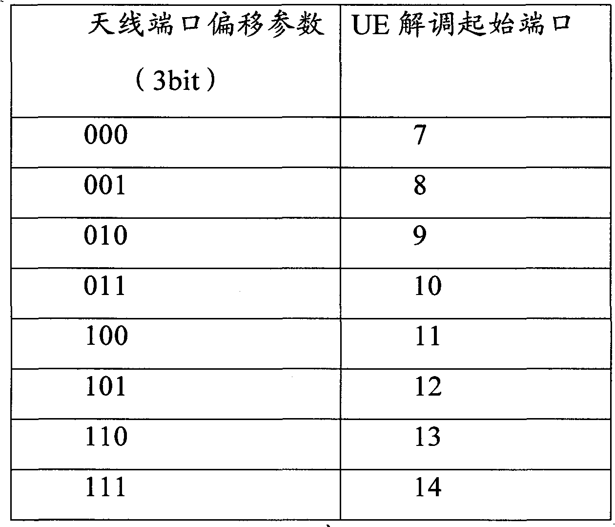
[0021] The network side determines the antenna port offset parameter corresponding to the start port of the antenna port resource according to the preset antenna port offset parameter-start port mapping table, and sends the UE carrying the antenna port offset parameter control signaling; ...


PUM


Abstract

The invention provides a configuration method of an antenna port. The method comprises the following steps that: when user equipment (UE) accesses a network, a network side determines antenna port resources used by the UE according to rules of configuring different antenna ports by different UE, and the network side informs the UE of configured antenna port resources by using control signaling. By the method provided by the invention, the interference problem among the UE during data receiving is effectively removed.

Description

technical field [0001] The present invention relates to the resource configuration technology in the mobile communication system, in particular to the antenna port configuration method in the multi-user-multi-input multi-output system. Background technique [0002] In the existing Long Term Evolution-Advanced system (LTE-A), user equipments (UEs) do not distinguish each other by antenna ports, but share all antenna ports. In this way, there will be a problem of interference between UEs during data reception. For example, for a certain user equipment UE1, the data Y received at the pilot position on its antenna port Port1 can be expressed by formula (1): [0003] Y=H 1 W 1 S 1 +H 1 W 2 S 1 +N Formula(1) [0004] Among them, H 1 is the channel response experienced by UE1, W 1 , W 2 are the precoding matrices adopted by UE1 and UE2 respectively, UE1 and UE2 are users on the current antenna port Port1, S 1 is the data sent at the pilot position, and N is Gaussian whi...

Claims


Application Information

Patent Timeline
IPC IPC(8): H04W16/18H04B7/04
CPCH04W48/08H04W24/02H04W28/048H04W28/04
Inventor 卫瑞平
Owner NEW POSTCOM EQUIP
Why Eureka
Try Eureka