Coil insertion method and coil insertion device

A coil insertion and coil technology, which is applied in the direction of prefabricated windings embedded in motors, can solve the problems of high end coils, additional parts, and unsuitable multi-phase coils, etc., and achieve the effects of reducing insertion resistance, saving coils, and high-efficiency stators

Active Publication Date: 2011-08-31
SHANGHAI HITACHI ELECTRICAL APPLIANCES CO LTD
View PDF3 Cites 13 Cited by
  • Summary
  • Abstract
  • Description
  • Claims
  • Application Information

AI Technical Summary

Problems solved by technology

[0004] However, when the above-mentioned coil insertion method is adopted, the coil insertion mechanism must have a movable brand groove in addition to the fixed brand groove and the embedded wire stripper, which increases the number of parts.
Also, when the above-mentioned coil insertion method is applied to multi-phase coils inserted at the same time, the coils hung on the thicker brandy grooves will make the end coils become taller due to the thickness, so the above-mentioned technique is not suitable for multi-phase

Method used


Image

  • Coil insertion method and coil insertion device
  • Coil insertion method and coil insertion device
  • Coil insertion method and coil insertion device

Examples


Embodiment 1

[0035] For the purpose of shortening the height of the end coil protruding from the end face of the stator core, the curved part of the upper end of the coil that is inserted into the slot first is expanded. A space where the inside of the curved portion of the coil does not conflict with the outside of the curved portion of the upper end of the coil inserted into the slot later.

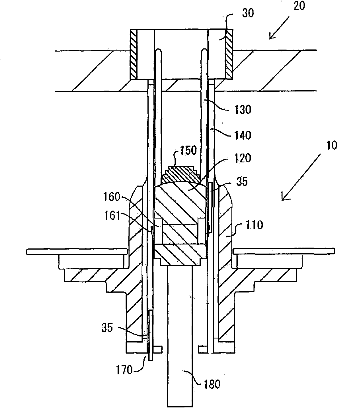
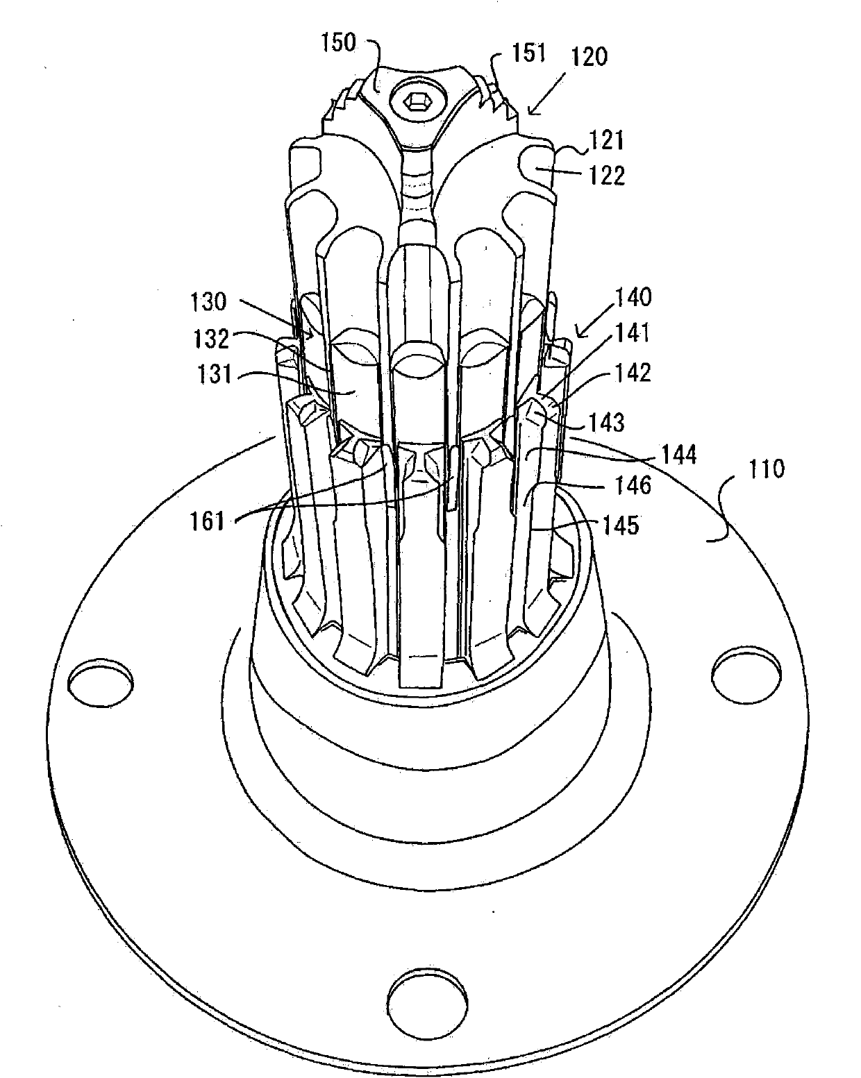
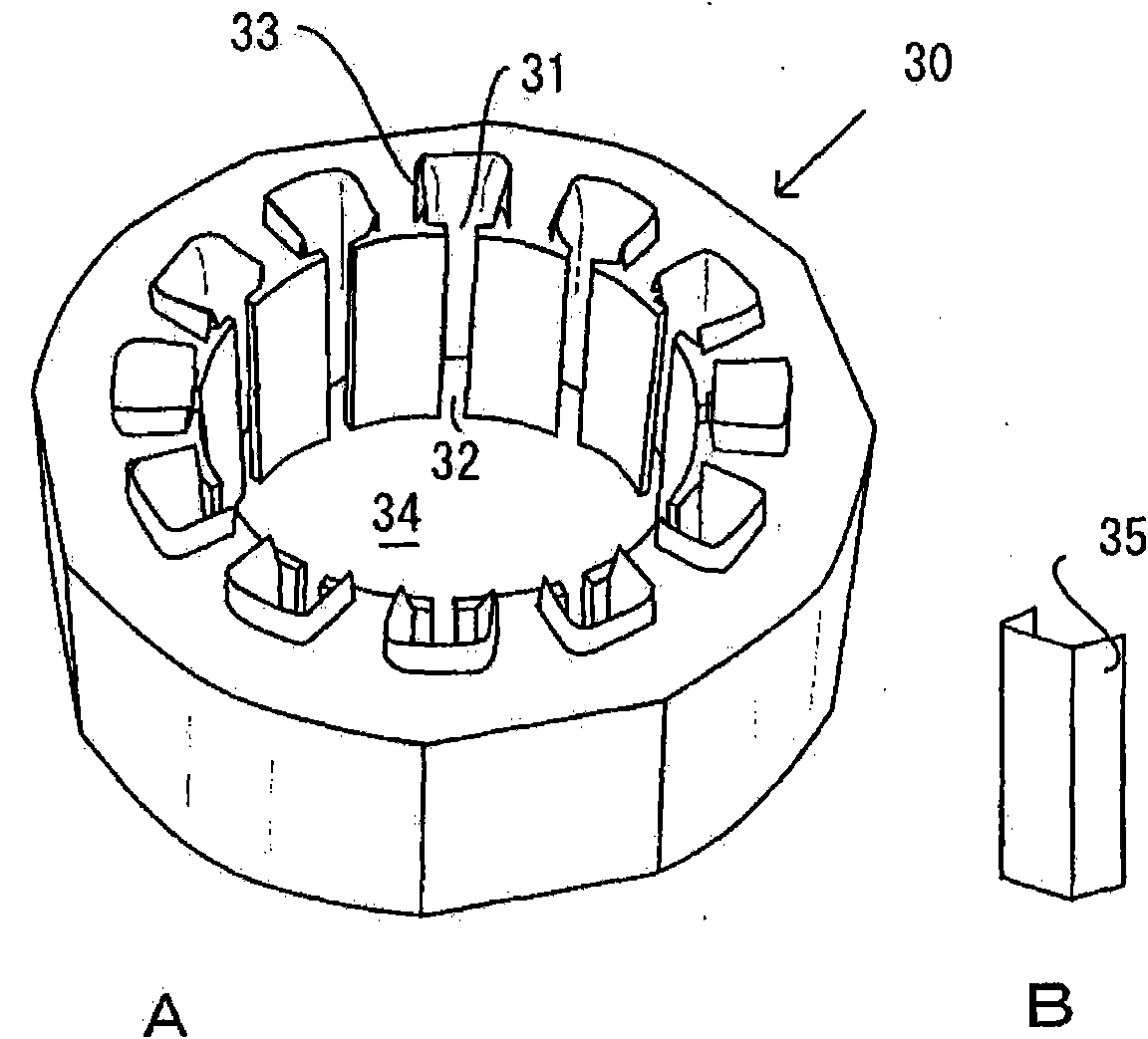
[0036] figure 1 It is a diagram illustrating the coil insertion mechanism 10 of the coil insertion device of the present invention through a longitudinal section, figure 2 It is a perspective view of the coil insertion mechanism 10 of the present invention, image 3 It is a perspective view of the stator core 30, and the perspective view of the coil insertion mechanism 10 shows the state in which the wire stripper 120 extended upwards for easy understanding of the whole. Figure 4 is a horizontal cross-sectional view of the coil insertion mechanism.

[0037] Such as image 3 As shown, a plurali...

Embodiment 2

[0073] This embodiment 2 replaces the coil expansion mechanism of embodiment 1, and its upper part is equipped with an inclined expansion mechanism for separating from the axis of the stator core while forming a curved surface at the part in contact with the coil curve above the stator core. The coil expansion mechanism of the guide part 250. The coil protruding from above the stator core is expanded along the expansion guide part 250 forming the above-mentioned curved surface, and the coil is expanded outward from the axial center of the stator core.

[0074] Figure 12 It is an explanatory diagram of the key parts of the stator core fixing mechanism with the coil expansion mechanism installed through the cross-section. The stator core 30 is sandwiched by a stator core fixing portion composed of the lower fixing portion 21 and the upper fixing portion 23 . The upper fixing part 23 is only at the upper position of the coil suspended above among the multi-phase coils, and the...


PUM


Abstract

The invention relates to a coil insertion method and a coil insertion device. In the process of embedding a polyphase coil in a stator core groove and under the state that a coil curve part protrudes from the stator core top end, the curve part is expanded towards the direction deviating a stator core axle center, and the coil at the lower part and the coil at the upper part do not conflict with each other. The coil insertion device is provided with a coil end expansion means implementing the above method. Even when a polyphase coil is inserted, a coil insertion method and a coil insertion device which can reduce the height of the coil at the end part which protruding from the stator core end face.

Description

technical field [0001] The present invention relates to a coil insertion method and a coil insertion device for inserting a pre-wound coil into a slot of a stator core, and more specifically relates to an expansion process and an expansion method for an inserted coil end. Background technique [0002] A conventional coil insertion device for inserting a coil into a stator core slot and a coil insertion method using the device are well known. The coil insertion method has better workability than the direct winding method, but has a disadvantage that the height of the end coil protruding from the end surface of the stator core is high. [0003] In order to solve this problem, Japanese Patent Application Publication No. 2003-230258 introduced movable brandy grooves and fixed brandy grooves around the embedding wire stripper, only by increasing the thickness of the movable brandy grooves that move synchronously with the embedding wire strippers. The technology of increasing the...

Claims


Application Information

Patent Timeline
IPC IPC(8): H02K15/06
Inventor 細野聖二
Owner SHANGHAI HITACHI ELECTRICAL APPLIANCES CO LTD
Why Eureka
Try Eureka