Long-distance guiding method for paradrop of cargo by transport plane

A long-distance, transport aircraft technology, applied in the field of transport aircraft navigation, can solve the problems that the expected total flight distance cannot be achieved, and there is no suitable method for determining the applicable conditions.

Inactive Publication Date: 2011-09-07
NORTHWESTERN POLYTECHNICAL UNIV
View PDF3 Cites 5 Cited by
  • Summary
  • Abstract
  • Description
  • Claims
  • Application Information

AI Technical Summary

Problems solved by technology

[0004] In order to overcome the deficiency that the prior art can only achieve the desired total flight time, but cannot reach the desired total flight distance, and does not have the applicable conditions for determining the method, the present invention provides a method by adjusting the distance and time of multiple constant-speed flight stages, which can Simultaneously achieve the desired total flight time and distance and apply the long-distance guidance method with clear conditions

Method used


Image

  • Long-distance guiding method for paradrop of cargo by transport plane
  • Long-distance guiding method for paradrop of cargo by transport plane
  • Long-distance guiding method for paradrop of cargo by transport plane

Examples


Embodiment 1

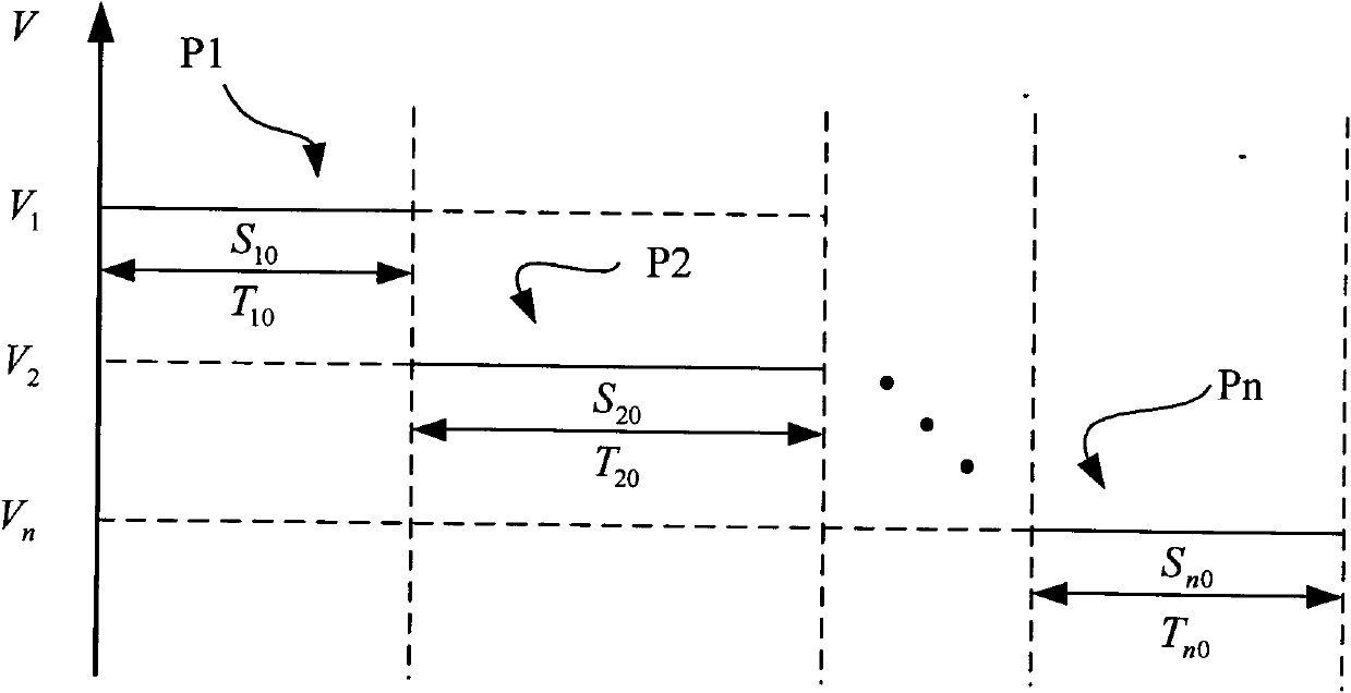
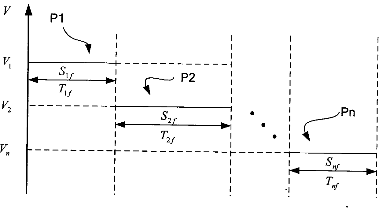
[0075] Known parameters: as attached figure 1 , there are 3 (n=3) constant speed phases P1, P2, and P3, P1 section speed V 1 =300m / s, the flight distance is S 10 =30000m, the flight time is T 10 =100s; P2 section speed is V 2 =200m / s, the flight distance is S 20 =16000m, the flight time is T 20 =80s; P3 stage speed is V 3 =100m / s, the flight distance is S n0 =6000m, the flight time is T 30 =60s; obviously the total flight distance S of the original plan 0 =52000m and time T 0 =240s; as attached figure 2 , the expected total flight distance S f =80000m and time T j = 540s.

[0076] Unknown parameter: as attached figure 2 , find S if (i=1, 2, 3), T if (i=1, 2, 3).

[0077] The program implementation process is as follows:

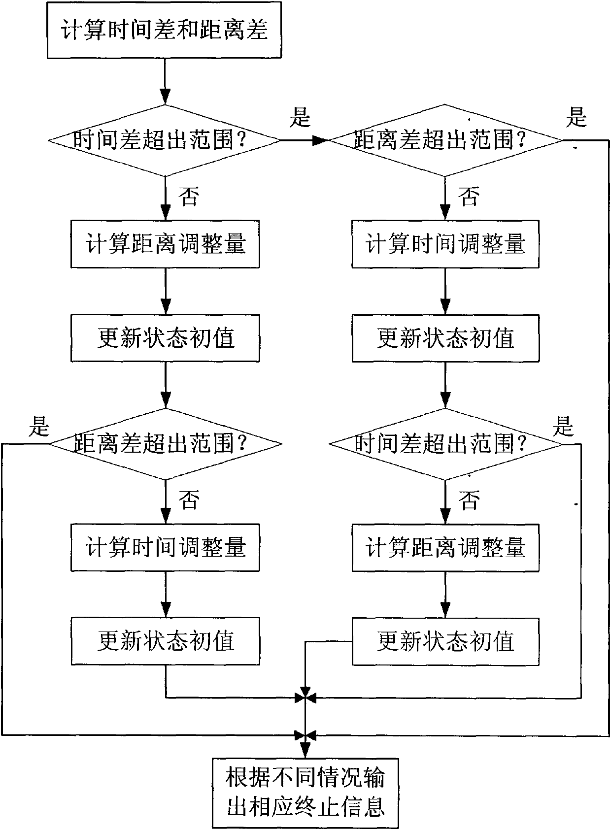
[0078] Step 1: According to the original planned total flight distance S 0 and time T 0 and the expected total flight distance S f and time T f , calculate the flight distance difference ΔS and the time difference ΔT.

[0079] ...

Embodiment 2

[0084] Known parameters: as in Example 1, keeping other parameters unchanged, the expected total flight distance S f =60000m and time T f = 640s.

[0085] Unknown parameter: S if (i=1, 2, 3), T if (i=1, 2, 3).

[0086] The program implementation process is as follows:

[0087] Step 1: According to the original planned total flight distance S 0 and time T 0 and the expected total flight distance S f and time T f , calculate the flight distance difference ΔS and the time difference ΔT.

[0088] ΔS = S f - S 0 = 8000 m ΔT = T f - T 0 = ...

Embodiment 3

[0095] Known parameters: as in Example 1, keeping other parameters unchanged, the expected total flight distance S f =60000m and time T f = 540s.

[0096] Unknown parameter: S if (i=1, 2, 3), T if (i=1, 2, 3).

[0097] The program implementation process is as follows:

[0098] Step 1: According to the original planned total flight distance S 0 and time T 0 and the expected total flight distance S f and time T f , calculate the flight distance difference ΔS and the time difference ΔT.

[0099] ΔS = S f - S 0 = 8000 m ΔT = T f - T 0 = ...


PUM


Abstract

The invention discloses a long-distance guiding method for the paradrop of cargo by a transport plane, which comprises the following steps of: computing a distance difference and a time difference according to an original total flying distance and time and a desired total flying distance and time; firstly regulating the distance at each constant-speed stage to eliminate the time difference, updating a state initial value after regulating the distance at each constant-speed stage; then regulating the time at each constant-speed stage to eliminate the distance difference, and updating a state initial value after regulating the time at each constant-speed stage; ending the steps when achieving an regulating target; and when the time difference or the distance difference required to eliminateis over a critical range and the regulating target cannot be achieved, ending the method. The long-distance guiding method can adapt to a condition that the distance difference and the time difference are in coexistence so that the desired total flying time and the desired total flying distance can be achieved simultaneously.

Description

technical field [0001] The invention belongs to the field of transport aircraft navigation, in particular to a guidance method for air-dropped goods by transport aircraft. Background technique [0002] In order to successfully airdrop cargo, the transport aircraft must: determine the flight speed, time and distance of each flight stage during mission planning; adjust the flight speed, time and distance of each stage according to real-time conditions during online flight. From the entry point of the airdrop area to the starting point of aiming, the transport aircraft has a process of reducing speed and altitude, which is called the deceleration and heightening stage, and the navigation in this stage is called long-distance guidance. During mission planning, a guidance process is generated, called the original plan guidance process, including several constant-speed flight stages and their adjacent deceleration stages; the sum of the flight time of all constant-speed flight sta...

Claims


Application Information

Patent Timeline
Patent Type & Authority Applications(China)
IPC IPC(8): G05D1/10
Inventor 张安汤志荔刘存
Owner NORTHWESTERN POLYTECHNICAL UNIV
Why Eureka
Try Eureka