Clock signal generating device and analog-digital conversion device

a clock signal and analog-digital conversion technology, applied in the direction of generating/distributing signals, pulse techniques, instruments, etc., can solve the problems of affecting the accuracy of analog-digital conversion, so as to improve analog-digital conversion precision and eliminate the difference in sampling time between the a and b channels.

Active Publication Date: 2009-10-27
PANASONIC SEMICON SOLUTIONS CO LTD
View PDF11 Cites 4 Cited by
  • Summary
  • Abstract
  • Description
  • Claims
  • Application Information

AI Technical Summary

Benefits of technology

[0029]Furthermore, according to the A / D conversion device having the interleaved constitution using the clock signal generating device, the two clock signals having the mutually inverted signal waveforms having the phase difference of just 180° in the clock signal generating device can be used for switching the sampling and holding timings of the A and B channels, respectively. Thus, the sampling time difference between the A and B channels can be eliminated and analog-digital conversion precision can be improved.

Problems solved by technology

Although high-speed A / D conversion is realized by the interleaved constitution, the problem is that when the sampling timing difference is generated between both A / B channels, the characteristics are degraded because of the timing difference.
Therefore, the problem is that a difference in sampling time is caused between both channels in the A / D converter having the interleaved constitution using the above device.
Thus, the analog-digital conversion precision is degraded due to an error caused by the difference in sampling time between the A channel and the B channel.

Method used


Image

  • Clock signal generating device and analog-digital conversion device
  • Clock signal generating device and analog-digital conversion device
  • Clock signal generating device and analog-digital conversion device

Examples


first embodiment

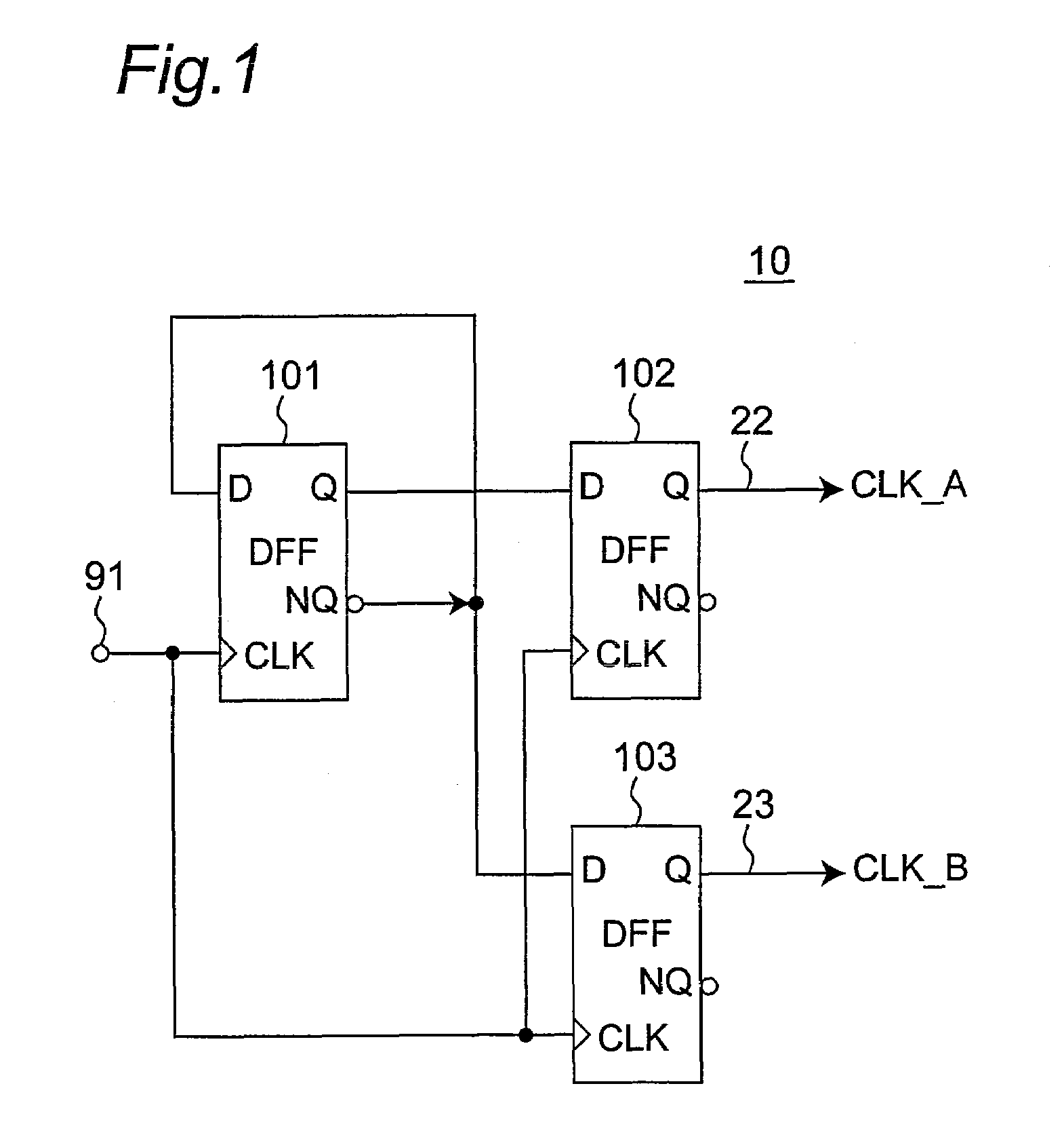
[0040]FIG. 1 is a circuit diagram showing a constitution of a clock signal generating device 10 according to first embodiment of the present invention. The clock signal generating device 10 includes three Delayed Flip Flops 101 to 103. In addition, it includes a master clock signal input terminal 91 and two output terminals 22 and 23. A master signal is divided into two clock signals having mutually inverted signal waveforms in which their phase difference is 180° and the two clock signals are outputted at the same time from the two output terminals 22 and 23.

[0041]Next, the clock signal generating device 10 will be described in detail.

[0042]First, the master clock signal input terminal 91 is connected to a clock terminal of the first Delayed Flip Flop 101, a clock terminal of the second Delayed Flip Flop 102, and a clock terminal of the third Delayed Flip Flop 103. In addition, an inversion output terminal (NQ) of the first Delayed Flip Flop 101 is connected to a D input terminal o...

second embodiment

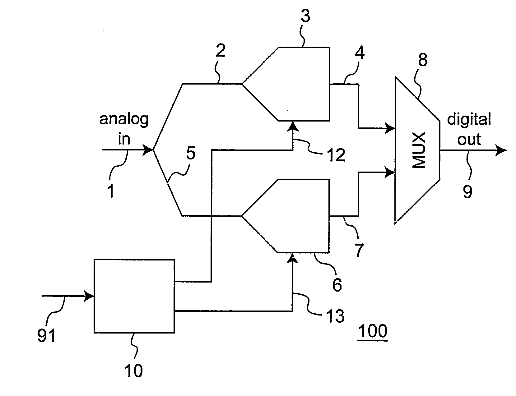
[0055]FIG. 3 is a block diagram showing a constitution of an analog-digital (A / N) conversion device100 having an interleaved constitution according to second embodiment of the present invention. FIG. 4 is a block diagram showing a detailed constitution when the clock signal generating device 10 according to first embodiment is used as a clock signal generating device shown in FIG. 3. The characteristic of the A / D conversion device 100 is to include the clock signal generating device 10 according to first embodiment of the present invention. Furthermore, the A / D conversion device 100 includes the clock signal generating device 10, an analog signal input terminal 1, a one-side (A channel-side) A / D converter 3, the other-side (B channel-side) A / D converter 6, a multiplexer circuit 8, and a digital signal output terminal 9. Since the constitution of the clock signal generating device 10 is the same as the clock signal generating device 10 according to first embodiment of the present inv...


PUM


Abstract

A first Delayed Flip Flop includes a first D input terminal, a first clock input terminal, a first output terminal outputting a signal inputted to the first D input terminal based on the clock signal, and a first inversion output terminal inverting and outputting the signal inputted to the first D input terminal and outputting the signal to the first D input terminal as a feedback. A second Delayed Flip Flop includes a second D input terminal receiving the output from the first output terminal of the first Delayed Flip Flop, a second clock input terminal, and a second output terminal outputting the signal inputted to the second D input terminal as a first output based on the clock signal. A third Delayed Flip Flop includes a third D input terminal receiving the output from the first inversion output terminal of the first Delayed Flip Flop, a third clock input terminal, and a third output terminal outputting the signal inputted to the third D input terminal as a second output based on the clock signal. The first output and the second output have signal waveforms inverted at the same timing.

Description

BACKGROUND OF THE INVENTION[0001]1. Field of the Invention[0002]This application claims priority based on Japanese Patent Application No. 2006-351203 filed in Japan on Dec. 27, 2006, the disclosure of which is incorporated herein by reference.[0003]The present invention relates to a clock signal generating device and an analog-digital conversion device including the clock signal generating device.[0004]2. Description of the Related Art[0005]In recent years, a technique for A / D conversion with high precision and at high speed in a communication filed such as a wireless LAN or a imaging technique such as a digital TV has been required. Among techniques to speed up the A / D conversion, there is an interleaved constitution in which A / D converters of both A / B channels are processed in parallel in a time-division manner, and a double sampling technique in which an operation amplifier is commoditized among the interleaves, as described in “Low-Power Pipeline ADC for Wireless LANs”, IEEE Jou...

Claims


Application Information

Patent Timeline
Patent Type & Authority Patents(United States)
IPC IPC(8): H03M1/12
CPCG06F1/06H03M1/0624H03K5/151H03M1/1215
Inventor MAKABE, YOSHIKAZUHIDAKA, IKUOOKA, KOJIOZEKI, TOSHIAKI
Owner PANASONIC SEMICON SOLUTIONS CO LTD
Why Eureka
Try Eureka