Eureka AIR delivers breakthrough ideas for toughest innovation challenges, trusted by R&D personnel around the world.

Droplet discharging head and droplet discharging device

a technology of droplet and discharging device, which is applied in printing and other directions, can solve the problems of reducing the efficiency of liquid material supply to the cavity, nozzles ejecting droplets without sufficient material supply, etc., and achieves uniform efficiency of material supply, reduces variation in material supply, and alleviates time difference

Inactive Publication Date: 2010-10-12
SEIKO EPSON CORP
View PDF19 Cites 1 Cited by
  • Summary
  • Abstract
  • Description
  • Claims
  • Application Information

AI Technical Summary

Benefits of technology

The invention relates to a droplet discharging head for a device that discharges liquid material. The technical effects of the invention include reducing variation in the supply of material to each nozzle, improving efficiency in supply, and reducing variation in the time for material to reach each nozzle. The droplet discharging head includes a reservoir, ink supply passages, and liquid chambers connected through ink supply passages, and nozzle portions connected to each liquid chamber. The normal line (the distance from the outer circumference of the reservoir to the connection between the liquid chamber and the ink supply passage) is shorter for a liquid chamber connected to a different ink supply passage, which helps to achieve a more uniform supply of material to each liquid chamber. The reservoir can have a curved surface and different lengths for the ink supply passages, which further enhances the efficiency of supply. The droplet discharging device includes the droplet discharging head and a reservoir arrangement that allows for a high density of nozzles and reservoirs.

Problems solved by technology

However, if the reservoir is made smaller, resistance increases in the reservoir against the flow of the liquid material, thereby reducing the efficiency in supply of the liquid material to the cavity.
This may cause some nozzles to eject droplets without sufficient supply of the material.

Method used


Image

  • Droplet discharging head and droplet discharging device
  • Droplet discharging head and droplet discharging device
  • Droplet discharging head and droplet discharging device

Examples


first embodiment

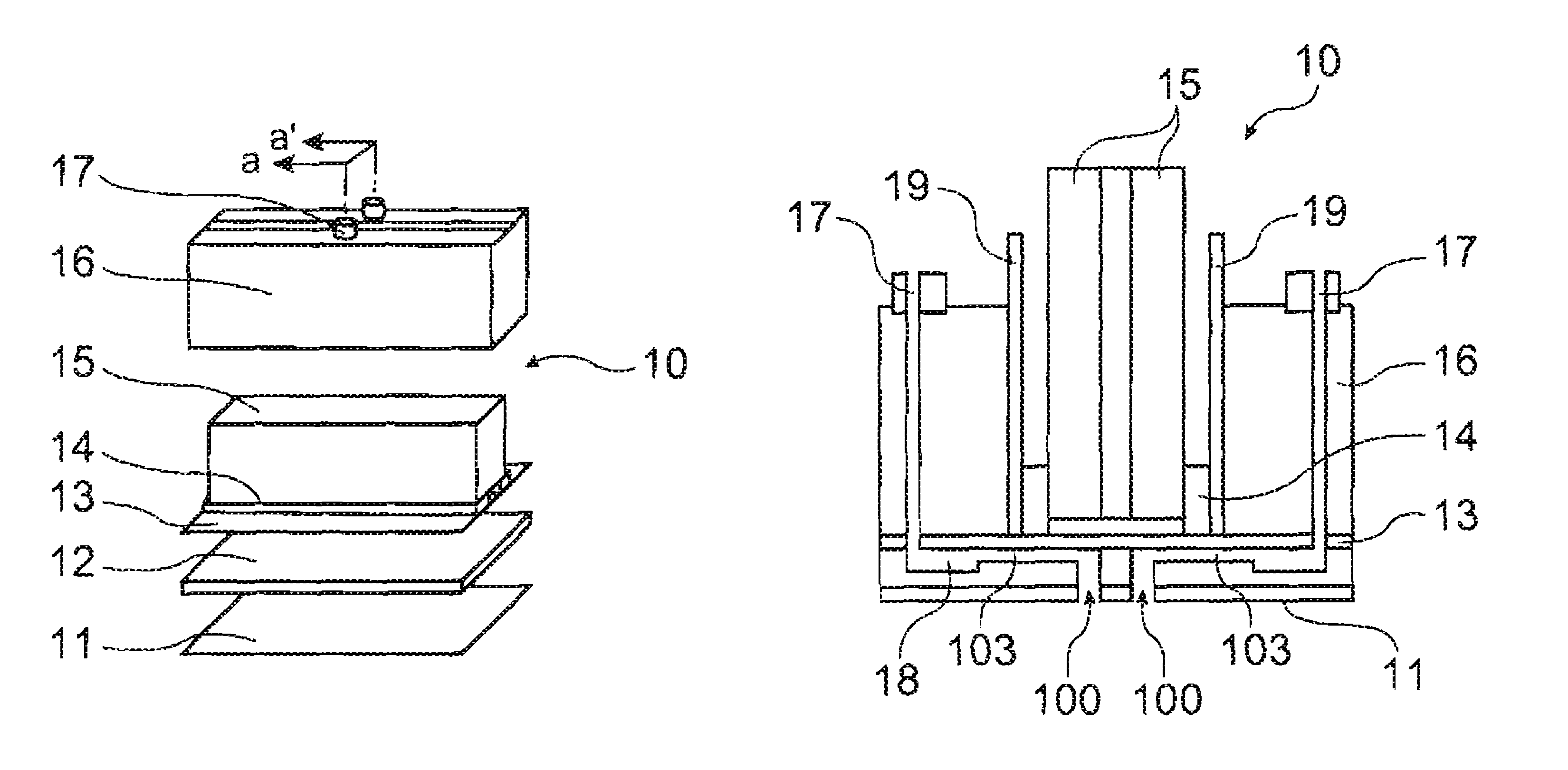
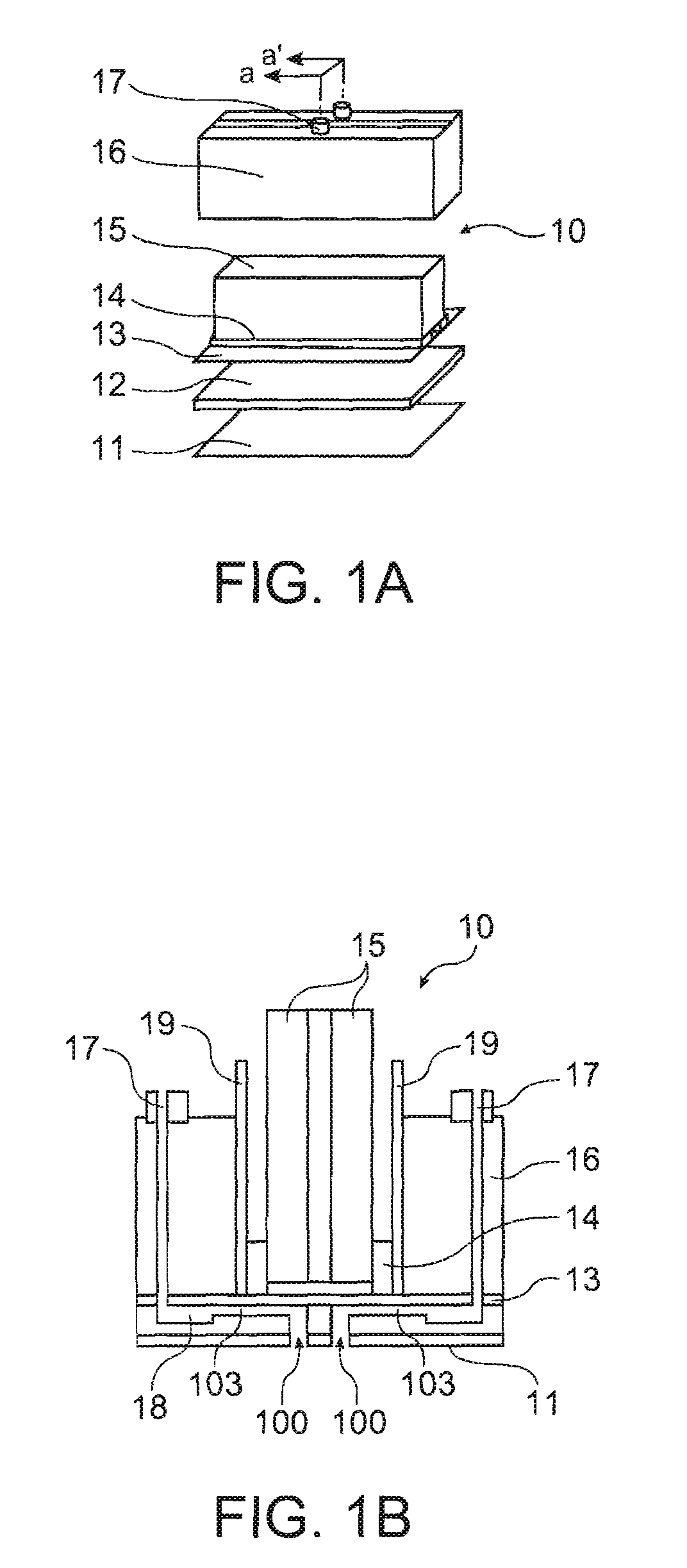
[0033]As shown in FIGS. 1A and 1B, a droplet discharging head 10 according to a first embodiment of the invention includes a nozzle plate 11, a flow path substrate 12, a diaphragm 13, piezoelectric elements 14, support substrates 15, a head case 16 and electrodes 19. Nozzle portions 100 are formed in the nozzle plate 11 and reservoirs 18, cavities (liquid chambers) 103 and ink supply passages 102 communicating the reservoirs 18 and the cavities are formed between the flow path substrate 12 and the diaphragm 13.

[0034]The structure of the droplet discharging head is not limited to one described above but may also be one in which the nozzle plate 11 and the flow path substrate 12 are integrally formed if the structure allows application of the relationship between the reservoirs 18, the cavities 103 and the ink supply passages 102 to be described below. Also, the nozzle portions 100 may be provided on the borderline between the flow path substrate 12 and the diaphragm 13.

[0035]The drop...

second embodiment

[0056]In a second embodiment, as shown in FIGS. 7A and 7B, a plurality of reservoirs 18 are disposed to form a zigzag shape. Since the reservoirs 18 are disposed in such a manner that they back against each other's material inlets 17, the cavities 103 are disposed on both the right and the left sides of the reservoirs 18.

[0057]In the second embodiment, as in the first embodiment, the longer the interval from the material inlet 17 is for a cavity 103 in Direction 2 perpendicular to Direction 1 that runs from the material inlet 17 toward the cavities 103, the shorter the interval from the material inlet 17 is for the cavity 103 in Direction 1.

[0058]In the same way as in the first embodiment, the droplet discharging head 10 according to the second embodiment of the invention allows the efficiency in supply of ink to each of the cavities 103 to be kept nearly uniform, thereby reducing variation in the supply of a material to each nozzle. In addition, the reservoirs 18 can be disposed wi...


PUM


Abstract

A droplet discharging head includes: a nozzle portion that discharges a liquid material; a liquid chamber that is in communication with the nozzle portion and supplies the liquid material to the nozzle portion in receiving a pressure from outside; and a reservoir that is in communication with a plurality of the liquid chamber through a plurality of ink supply passages and supplies the liquid material fed from outside via a material inlet to the plurality of liquid chambers. In the droplet discharging head, assuming that: a direction running from the material inlet toward the liquid chamber is a first direction; a direction perpendicular to the first direction is a second direction; a straight line passing through the material inlet in the first direction is a first reference line; and a straight line passing through the material inlet in the second direction is a second reference line, the longer a distance from the second reference line is for a liquid chamber, the shorter a distance from the first reference line is for the liquid chamber.

Description

BACKGROUND[0001]1. Field of the Invention[0002]Several aspects of the present invention relate to a droplet discharging head and a droplet discharging device.[0003]2. Related Art[0004]It is required that droplet discharging heads employed in droplet discharging devices including inkjet recorders discharges more minute droplets.[0005]In order to have an discharged droplet more minute, it is necessary to reduce the period of vibration in the cavity that supplies a liquid material to the nozzle in receiving pressures from outside through oscillation. In order, in turn, to reduce the period of vibration in the cavity, it is required that the entire flow path of a liquid material be made smaller. Such flow path includes the nozzle, the cavity and the reservoir that stores a liquid material to be supplied to the cavity.[0006]However, if the reservoir is made smaller, resistance increases in the reservoir against the flow of the liquid material, thereby reducing the efficiency in supply of...

Claims


Application Information

Patent Timeline
Patent Type & Authority Patents(United States)
IPC IPC(8): B41J2/05
CPCB41J2/175B41J2002/14419B41J2/01B41J2/135
Inventor OZAWA, KINYA
Owner SEIKO EPSON CORP
Why Eureka
Eureka Blog
Learn More