Three-Dimensional Scanner and Three-Dimensional Scanning Method
a three-dimensional scanner and scanning method technology, applied in the field of three-dimensional scanning, can solve the problems of inability to use, unsuitable promotion and use, and defects in the above-mentioned modes
- Summary
- Abstract
- Description
- Claims
- Application Information
AI Technical Summary
Benefits of technology
Problems solved by technology
Method used
Image

Examples
embodiment i
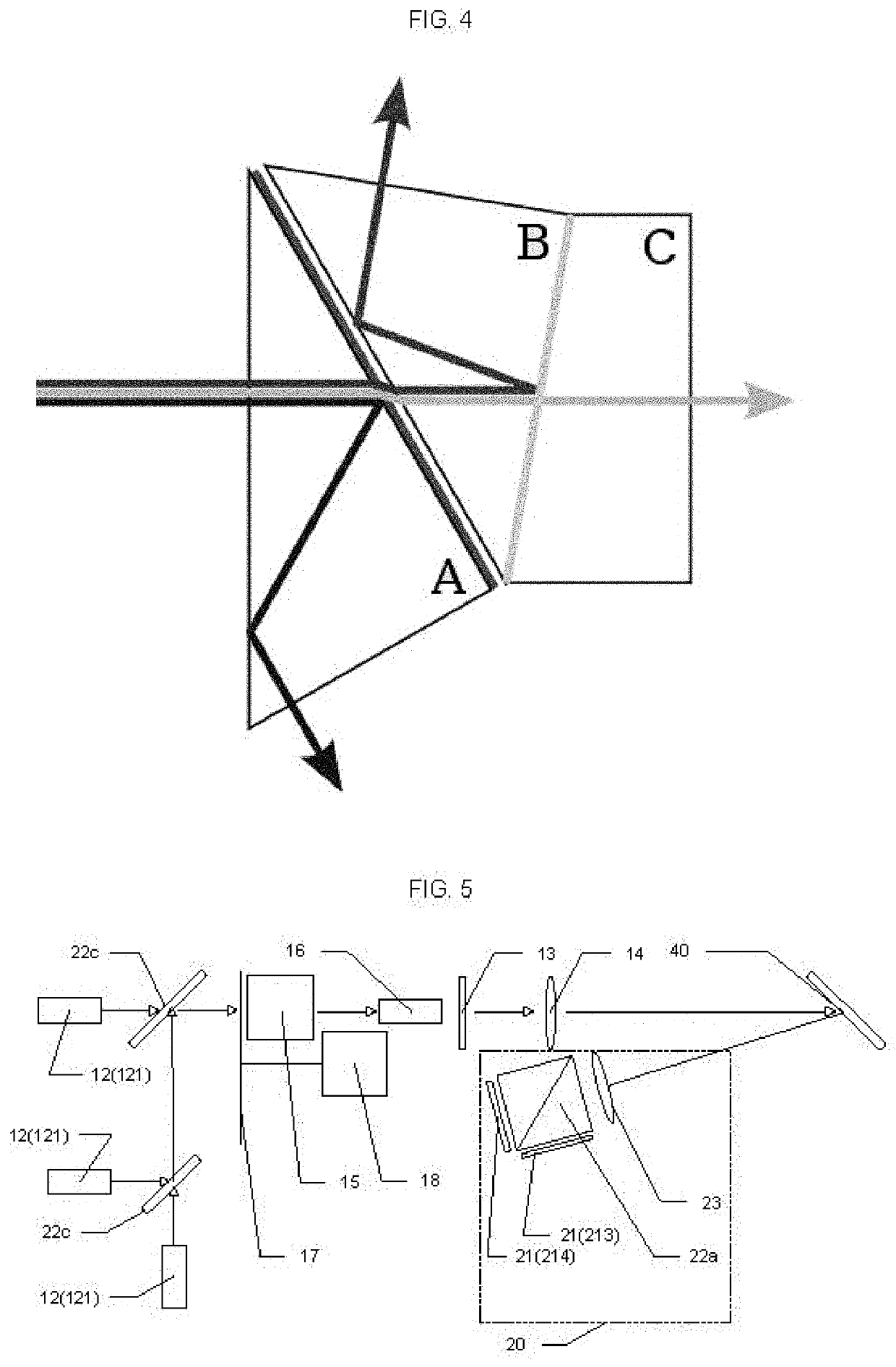
[0262]Taking FIG. 9 as an example, the beam processing device 22 includes a right-angled two-channel dichroic prism 22a, and the right-angled two-channel dichroic prism 22a includes a third light output portion and a fourth light output portion. The beam processing device 22 separates light projected from the light input portion through the right-angled two-channel dichroic prism 22a so that the light is respectively projected from the third light output portion and the fourth light output portion to cameras 21 corresponding to the respective light output portions.
[0263]Correspondingly, the image acquisition device 20 includes a third camera 213 corresponding to the third light output portion, and a fourth camera 214 corresponding to the fourth light output portion. The third camera 213 generates a third stripe image based on the acquired light. The fourth camera 214 generates a fourth stripe image based on the acquired light. The third stripe image and the fourth stripe image both ...
embodiment ii
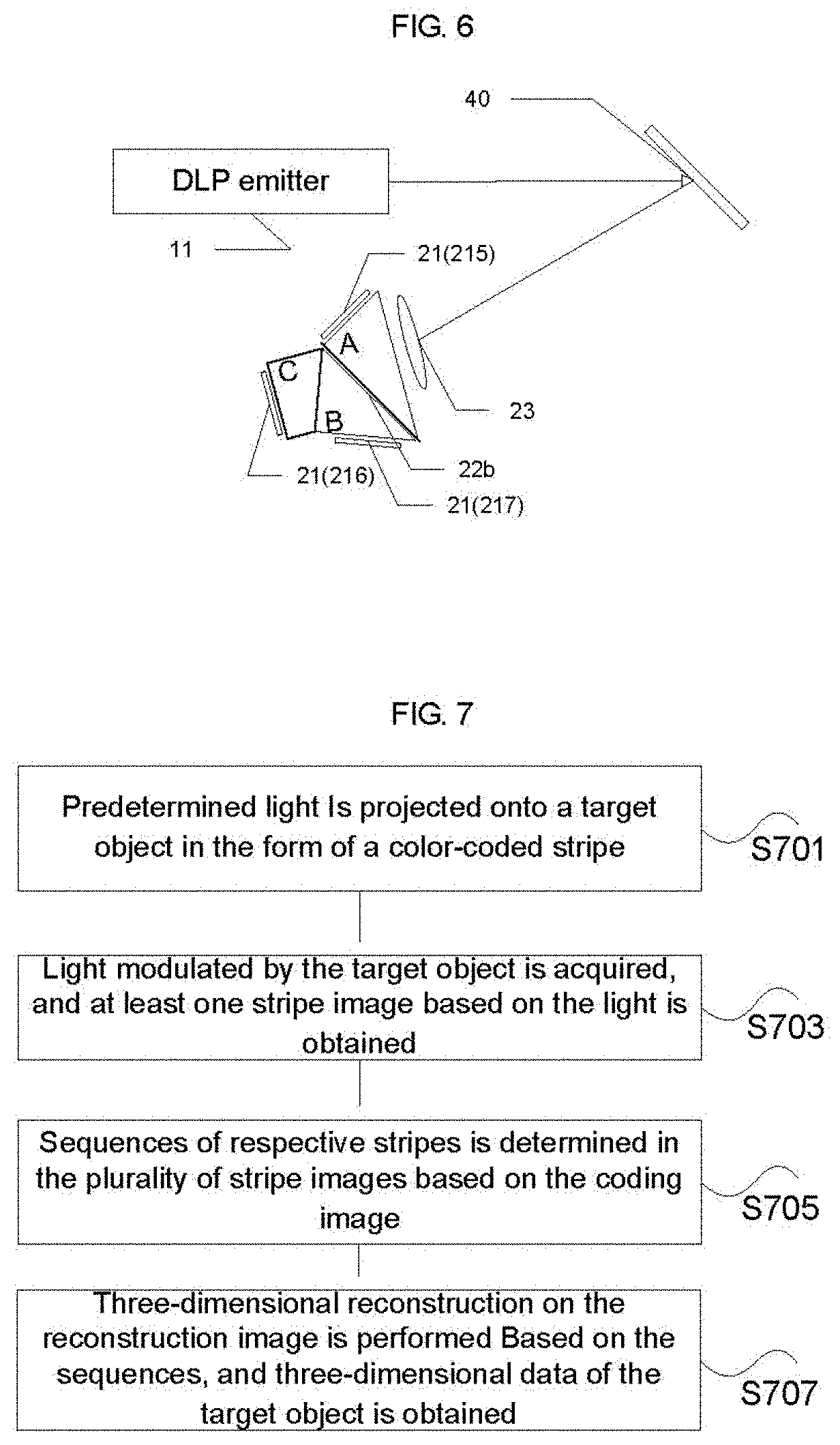
[0278]Taking FIG. 11 as an example, the beam processing device 22 includes a three-channel dichroic prism 22b, and the three-channel dichroic prism 22b includes a fifth light output portion, a sixth light output portion, and a seventh light output portion. The beam processing device 22 separates light projected from the light input portion through the three-channel dichroic prism 22b so that the light is respectively projected from the fifth light output portion, the sixth light output portion, and the seventh light output portion to cameras 21 corresponding to the respective light output portions.
[0279]Correspondingly, the image acquisition device 20 includes a fifth camera 215 corresponding to the fifth light output portion, a sixth camera 216 corresponding to the sixth light output portion, and a seventh camera 217 corresponding to the seventh light output portion. The fifth camera 215 generates a fifth stripe image based on the acquired light. The sixth camera 216 generates a si...
embodiment iii
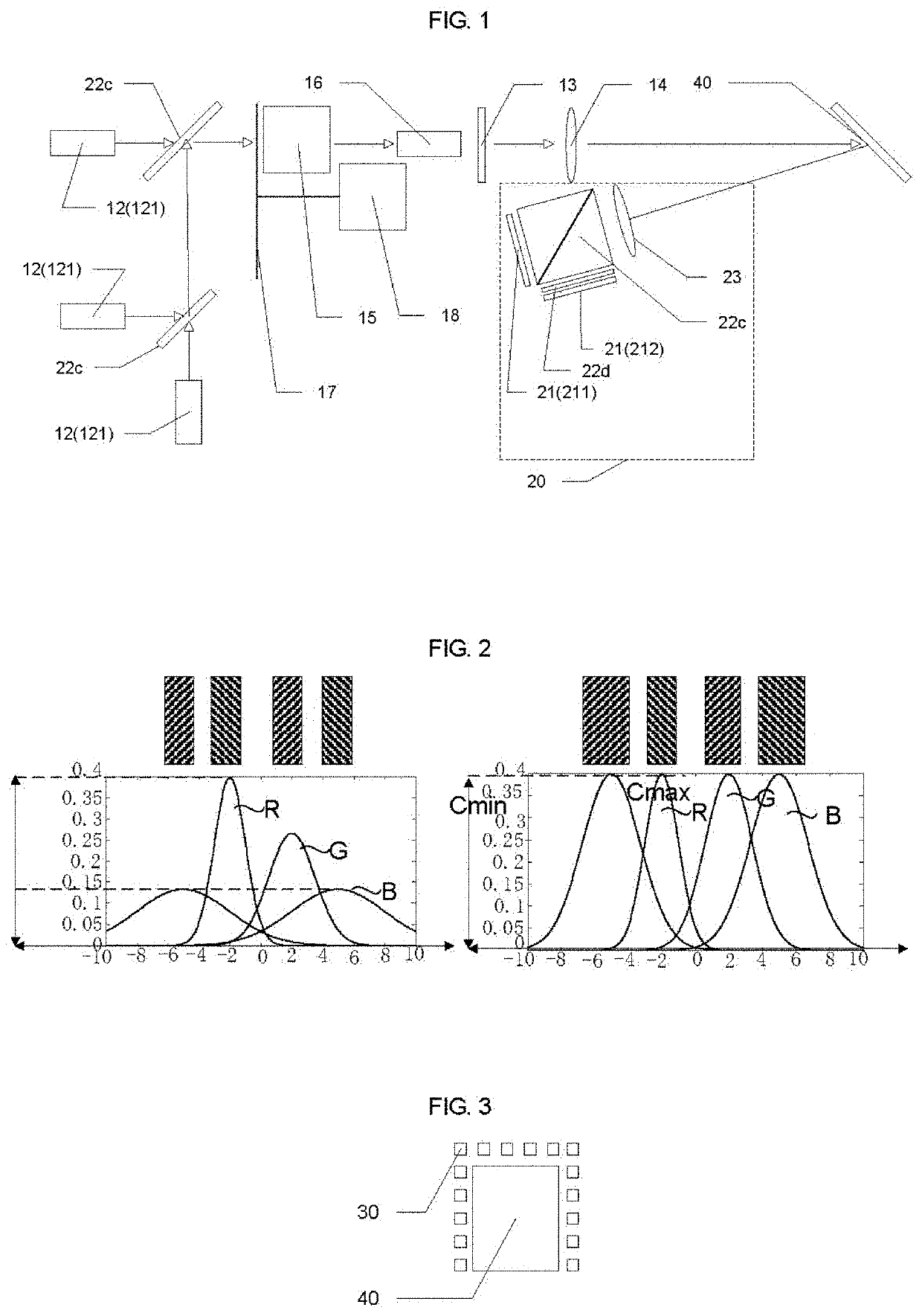
[0294]Taking FIG. 12 as an example, the beam processing device 22 includes a partial-reflection partial-transmission prism 22c, and the partial-reflection partial-transmission prism 22c includes a first light output portion and a second light output portion. The beam processing device 22 separates light projected from the light input portion through the partial-reflection partial-transmission prism 22c so that the light is respectively projected from the first light output portion and the second light output portion to cameras 21 corresponding to the respective light output portions.
[0295]Correspondingly, the image acquisition device 20 includes a first camera 211 corresponding to the first light output portion, and a second camera 212 corresponding to the second light output portion. The first camera 211 generates a first stripe image based on the acquired light. The second camera 212 generates a second stripe image based on the acquired light. The first stripe image and the second...
PUM
 Abstract
Description
Claims
Application Information
 - R&D
- Intellectual Property
- Life Sciences
- Materials
- Tech Scout
- Unparalleled Data Quality
- Higher Quality Content
- 60% Fewer Hallucinations
Browse by: Latest US Patents, China's latest patents, Technical Efficacy Thesaurus, Application Domain, Technology Topic, Popular Technical Reports.
© 2025 PatSnap. All rights reserved.Legal|Privacy policy|Modern Slavery Act Transparency Statement|Sitemap|About US| Contact US: help@patsnap.com