
Transfer apparatus, transfer network system, and transfer method

Inactive Publication Date: 2012-12-27
HITACHI LTD
View PDF7 Cites 1 Cited by
  • Summary
  • Abstract
  • Description
  • Claims
  • Application Information

AI Technical Summary

Benefits of technology

[0010]When data that has a great meaning in economic activities is disclosed to a plurality of users simultaneously by using a transfer network and a transfer apparatus, it is demanded that the differences in data disclosure time among the users be reduced to increase fairness.
[0011]Patent literature 1 and Patent literature 2 are known as technologies for reducing the differences in data disclosure time among users. However, since Patent literature 1 does not describe time synchronization control between a mobile terminal performing transfer control based on transfer time and another mobile terminal, synchronization precision, which directly affects the differences in data disclosure time among the users, is not clear. If the user changes the current time of a mobile terminal, he or she can receive disclosure data earlier than the other users. Patent literature 2 describes a time synchronization system between a server and a client. When the client receives information that includes the server current time, the additional software internal timer in the client is set to the received server current time. The time synchronization precision among clients depends on the differences in data transfer time from the server among the clients. Since the software controls data disclosure after the client receives the data, the data may be glanced earlier than the set data disclosure time.
[0012]Accordingly, it is an object of the present invention to reduce the differences in data disclosure time among users to increase fairness when data is disclosed to a plurality of users by using a transfer network and a transfer apparatus. Another object is to provide a high-precision data disclosure time control system by combining a high-precision (microsecond order) time synchronization system and data disclosure control. Still another object is to provide a system in which users cannot adversely affect data disclosure time control.
[0047]According to the present invention, the differences in data disclosure time among a plurality of users can be reduced to increase fairness when data is disclosed to the users by using a transfer network and a transfer apparatus. In addition, the users can be prevented from adversely affecting data disclosure time control. In one aspect of the present invention, the differences in data disclosure time among users are reduced in push technology service. In another aspect of the present invention, the differences in data disclosure time among users are reduced in pull technology service. In another aspect of the present invention, the concealment of data transferred in a transfer network is improved in a data disclosure time difference reduction system for users. In another aspect of the present invention, fairness is maintained if a transfer network or a transfer apparatus malfunctions in a data disclosure time difference reduction system for users. In another aspect of the present invention, fairness is increased in data receiving at user equipment in a data disclosure time difference reduction system for users. In another aspect of the present invention, fairness is maintained if user equipment malfunctions in a data disclosure time difference reduction system for users.

Problems solved by technology

However, since Patent literature 1 does not describe time synchronization control between a mobile terminal performing transfer control based on transfer time and another mobile terminal, synchronization precision, which directly affects the differences in data disclosure time among the users, is not clear.

Method used


Image

  • Transfer apparatus, transfer network system, and transfer method
  • Transfer apparatus, transfer network system, and transfer method
  • Transfer apparatus, transfer network system, and transfer method

Examples


first embodiment

1. First Embodiment

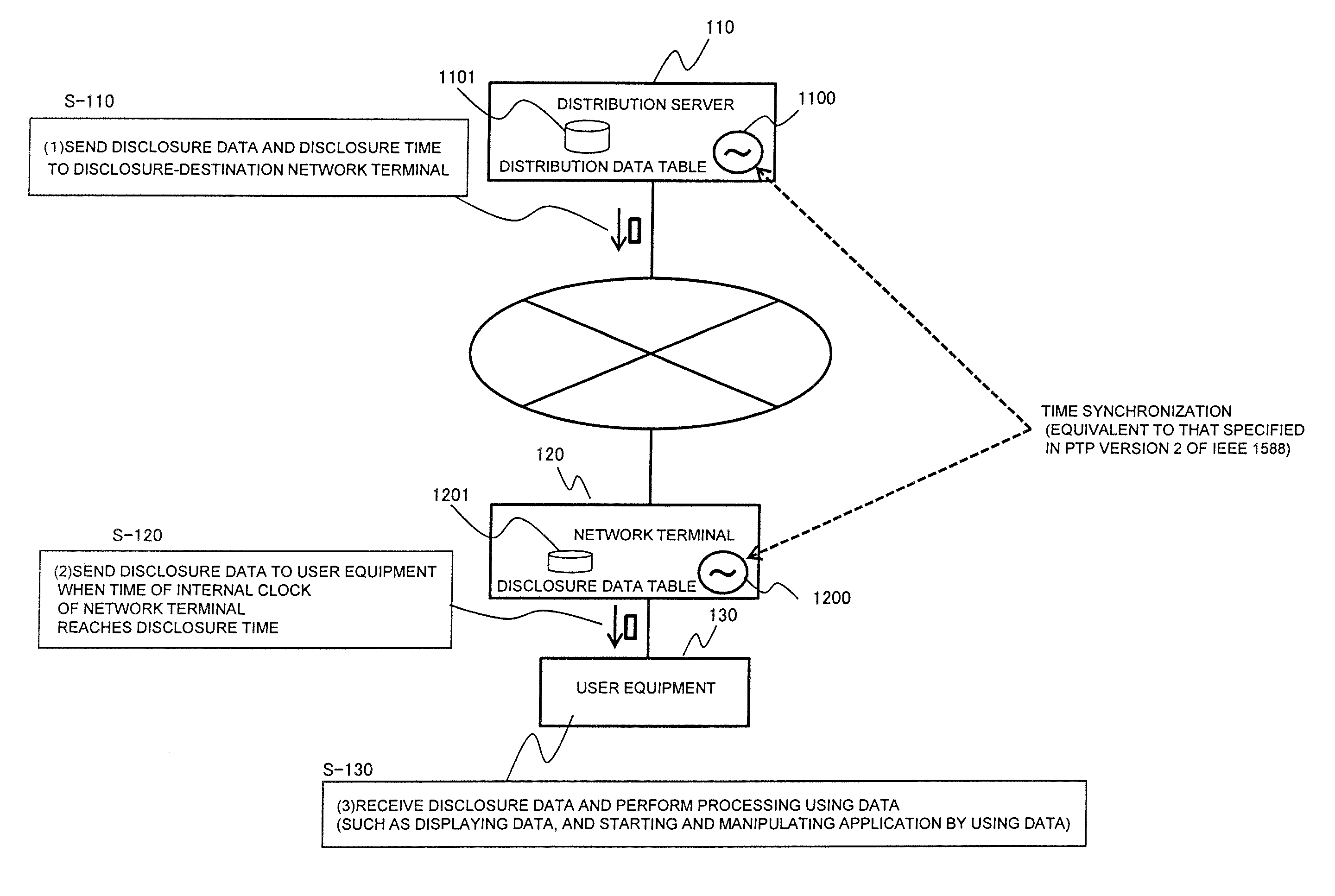
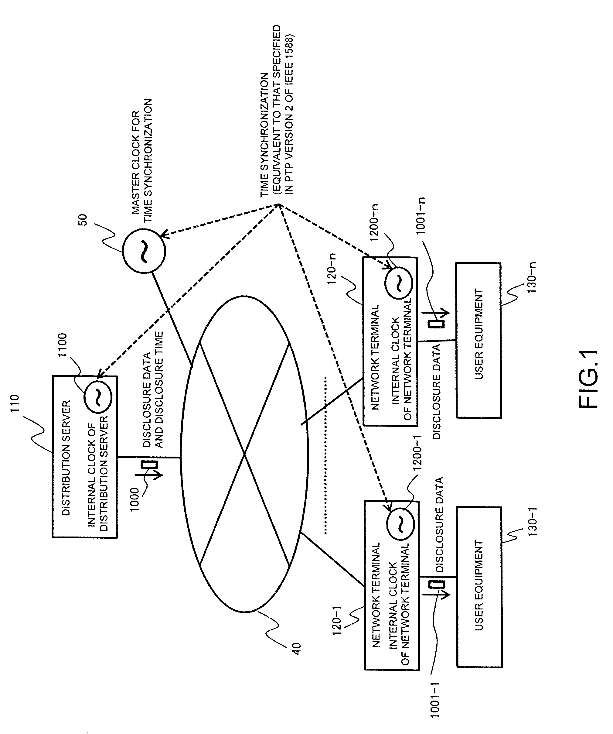
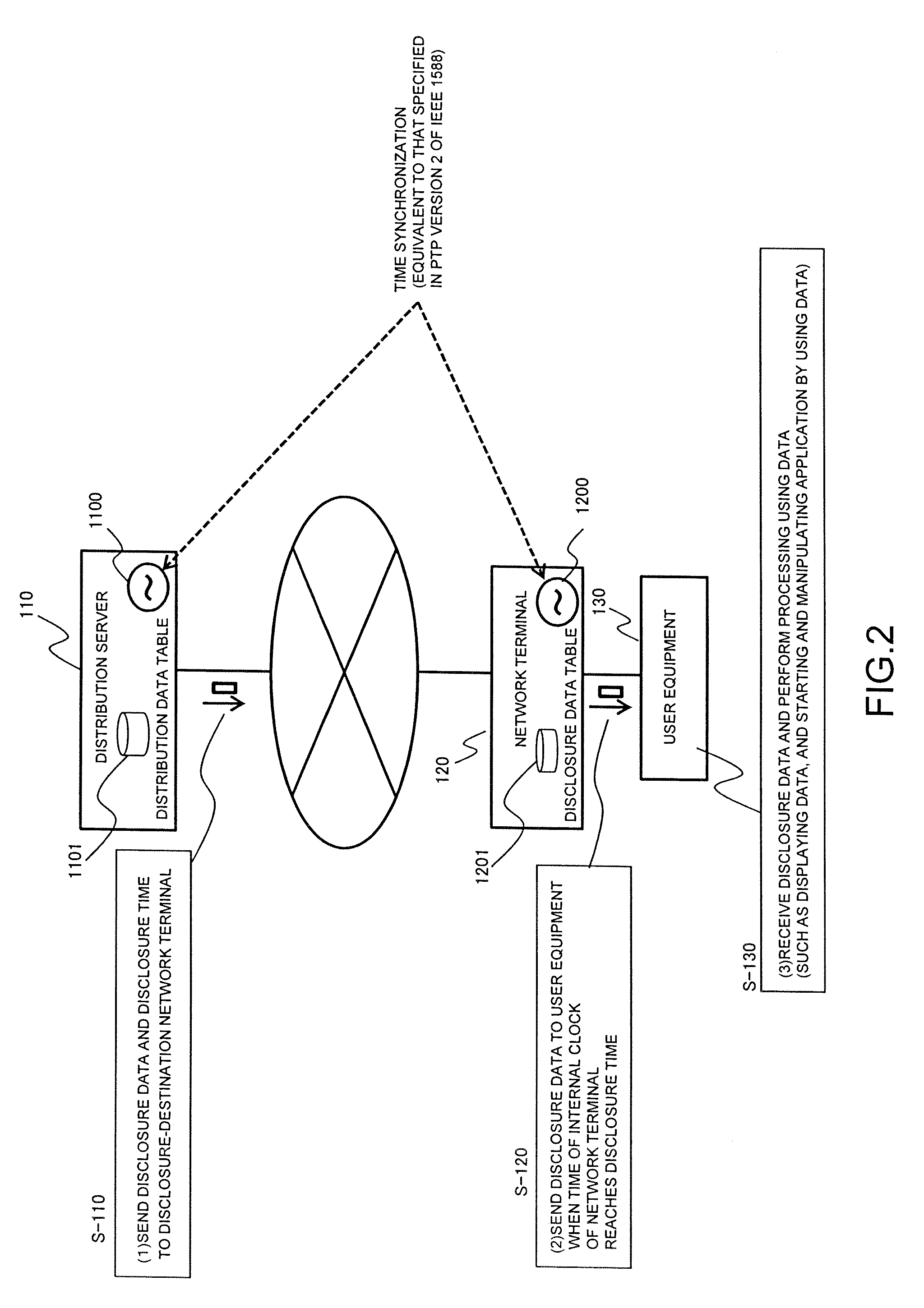
[0071]In the present embodiment, a transfer network system will be described in which a distribution server performs simultaneous data disclosure in a push technology service to a plurality of user equipment connected to the distribution server through a network terminal and a transfer network.

[0072]FIG. 1 is a view showing an example structure of the transfer network system of the present embodiment. In the figure, user equipment 130-1 to 130-n is connected to a distribution server 110 through network terminals 120-1 to 120-n, respectively, and a transfer network 40. Each of the distribution server 110 and the network terminals 120-1 to 120-n has a function to perform time synchronization with a master clock 50 for time synchronization through the transfer network 40. It is assumed that time synchronization is established between an internal clock 1100 of the distribution server 110 and internal clocks 1200-1 to 1200-n of the network terminals 120-1 to 120-n, and...

second embodiment

2. Second Embodiment

[0088]In the present embodiment, a transfer network system will be described in which a distribution server performs simultaneous data disclosure in a pull technology service to a plurality of user equipment connected to the distribution server through a network terminal and a transfer network. In the present embodiment, elements and operations different from and added to the first embodiment will be described below with reference to FIG. 5 and FIG. 6. The structure of the transfer network system of the present embodiment is the same as in the first embodiment, as shown in FIG. 1.

[0089]FIG. 5 is a view illustrating the operation of the transfer network system of the present embodiment. In the present embodiment, the distribution server sends disclosure data and disclosure time to the network terminal connected to the user equipment that has sent a data disclosure request in advance. The processing of a distribution server 210, a network terminal 220, and user equ...

third embodiment

3. Third Embodiment

[0092]In the present embodiment, a transfer network system will be described in which a distribution server performs simultaneous data disclosure to a plurality of user equipment connected to the distribution server through a network terminal and a transfer network, by encrypting data to be transferred and transferring it. In the present embodiment, elements and operations different from and added to the first embodiment or the second embodiment will be described below with reference to FIG. 7. The structure of the transfer network system of the present embodiment is the same as in the first embodiment or the second embodiment, as shown in FIG. 1 or FIG. 5.

[0093]FIG. 7 is a view illustrating the operation of the transfer network system of the present embodiment. In the present embodiment, when the distribution server sends disclosure data and disclosure time to the network terminal, the distribution server encrypts the disclosure data and the disclosure time to in...


PUM


Abstract

When data is disclosed to a plurality of users by using a transfer network and a transfer apparatus, data disclosure time control which cannot be adversely affected by the users is performed to reduce the difference in data disclosure time among the users. A transfer network system includes a distribution server serving as a data-distribution-source transfer apparatus, and a network terminal connected to distribution-destination user equipment. The distribution server and the network terminal each have a time keeping function and a time synchronization function for matching the time of the time keeping function with a master clock. The distribution server sends in advance disclosure data and disclosure time to the network terminal. When the time of the time keeping function of the network terminal matches the disclosure time, the network terminal sends the disclosure data to the user equipment.

Description

CLAIM OF PRIORITY[0001]The present application claims priority from Japanese patent application JP 2011-139146 filed on Jun. 23, 2011, the content of which is hereby incorporated by reference into this application.BACKGROUND OF THE INVENTION[0002]1. Field of the Invention[0003]The present invention relates to transfer apparatuses, transfer network systems, and transfer methods, and more particularly, to a transfer apparatus, a transfer network system, and a transfer method that are provided with a function to disclose data to a plurality of uses at the same time.[0004]2. Description of the Related Art[0005]Information transfer with the use of transfer networks, such as the Internet and leased lines, has been widely used in recent years also in economic activities including commerce. When important data is disclosed to users, such as news that can affect economic activities and an authentication key used to start a transaction, it is demanded that the differences in data disclosure t...

Claims


Application Information

Patent Timeline
IPC IPC(8): G06F15/16
CPCH04L67/1095H04L69/28H04L67/325H04L67/26H04L67/55H04L67/62
Inventor FUJIOKA, SHINYAASHI, YOSHIHIROMIZUTANI, MASAHIKO
Owner HITACHI LTD
Learn More