Eureka AIR delivers breakthrough ideas for toughest innovation challenges, trusted by R&D personnel around the world.

Light source driving device, lighting apparatus, and lighting control system

a technology of driving device and light source, which is applied in the direction of lighting apparatus, light sources, electrical appliances, etc., can solve the problem that data signals cannot be obtained in an area, and achieve the effect of reducing the timing difference between visible light communication operations

Active Publication Date: 2020-03-10
PANASONIC INTELLECTUAL PROPERTY MANAGEMENT CO LTD
View PDF13 Cites 0 Cited by
  • Summary
  • Abstract
  • Description
  • Claims
  • Application Information

AI Technical Summary

Benefits of technology

The present disclosure provides a way to reduce the timing difference for visible light communication operations. This can be implemented in a light source driving device, a lighting apparatus, and a lighting control system. The technical effect is to improve the reliability and efficiency of visible light communication operations.

Problems solved by technology

In this case, if the plurality of lighting apparatuses blink at different timings, there is a possibility that the data signal cannot be obtained in an area in which light rays emitted by the plurality of lighting apparatuses overlap with each other.

Method used


Image

  • Light source driving device, lighting apparatus, and lighting control system
  • Light source driving device, lighting apparatus, and lighting control system
  • Light source driving device, lighting apparatus, and lighting control system

Examples


embodiment 1

[0023][Configurations of a Lighting Control System and a Lighting Apparatus]

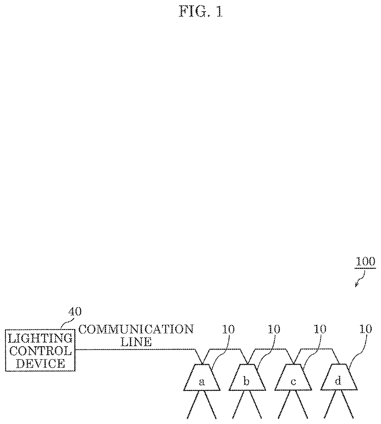
[0024]Hereinafter, the configurations of the lighting control system and the lighting apparatus according to Embodiment 1 are described with reference to the drawings. First, a lighting control system according to Embodiment 1 is described. FIG. 1 is a diagram illustrating configuration of the lighting control system according to Embodiment 1.

[0025]As illustrated in FIG. 1, lighting control system 100 according to Embodiment 1 includes a plurality of lighting apparatuses 10 and lighting control device 40. The total number of the plurality of lighting apparatuses 10 is four in FIG. 1, but the total number of lighting apparatuses 10 is not particularly limited. The plurality of lighting apparatuses 10 may be individually referred to as lighting apparatus a, lighting apparatus b, lighting apparatus c, and lighting apparatus d.

[0026]Lighting control device 40 is a controller for controlling the plurality of ligh...

embodiment 2

[0055][Reduction in Difference in Timing for Receiving Instruction Signal]

[0056]As another one of the causes that make the blinking timings for visible light communication different, it is conceivable that a difference in the lengths of a signal line to respective lighting apparatuses makes a difference in the timing at which respective lighting apparatuses receive the first instruction signal. In the example of FIG. 1, the length of the communication line from lighting apparatus a to lighting control device 40 is less than the length of the communication line from lighting apparatus d to lighting control device 40. Accordingly, lighting apparatus a receives the first instruction signal at a timing earlier than the timing for lighting apparatus d. In other words, the timing at which lighting apparatus a receives the first instruction signal and the timing at which lighting apparatus d receives the first instruction signal differ from each other. Such a difference in the reception ti...


PUM


Abstract

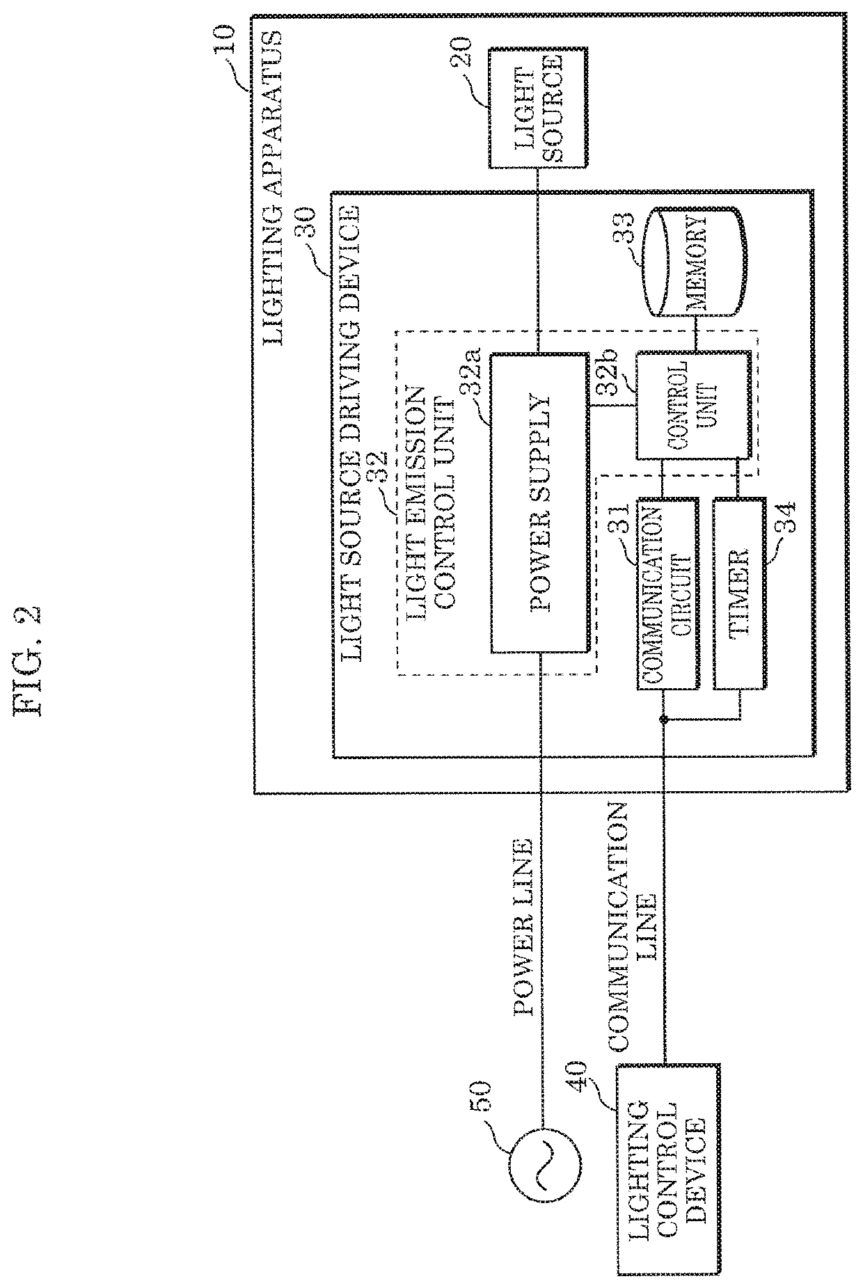
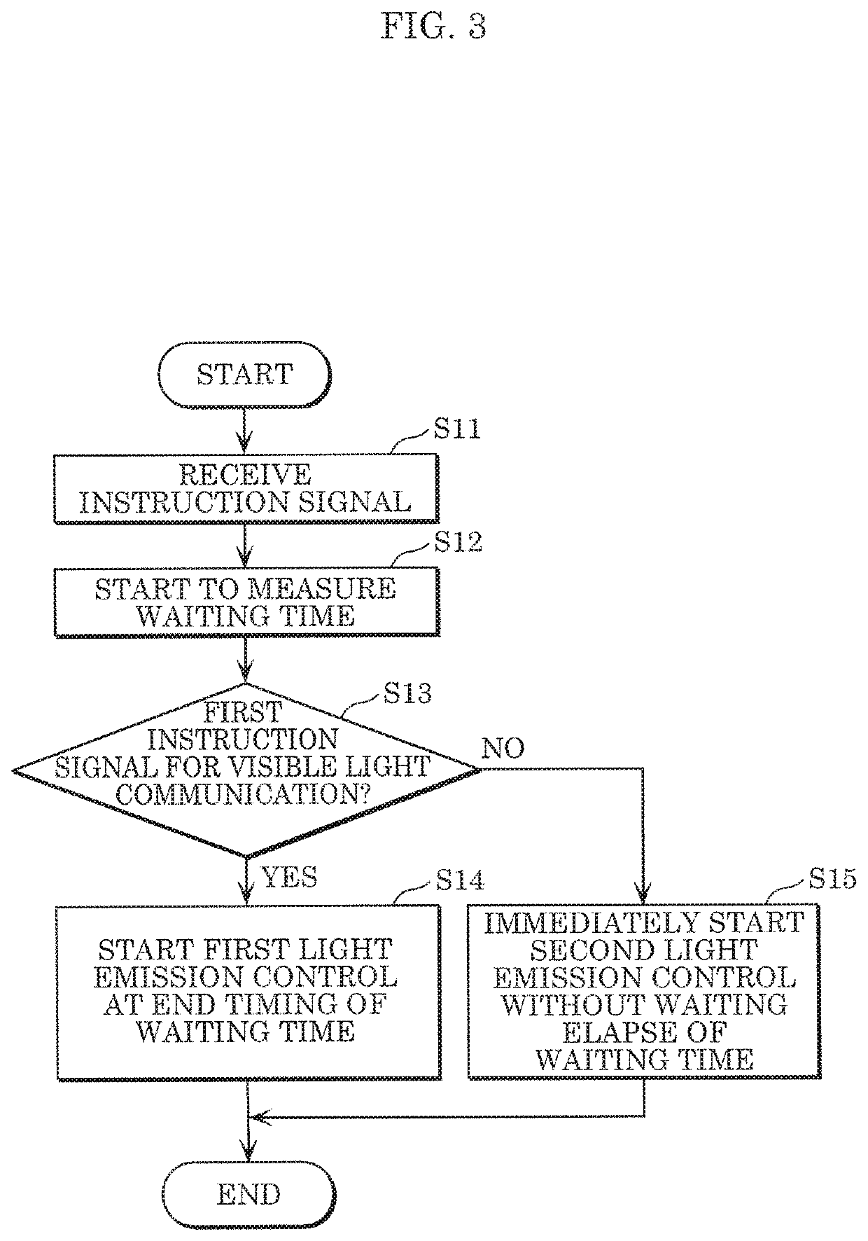
A light source driving device includes: a light emission control unit configured to control light emission of a light source in response to an instruction signal; a communication circuit which receives a first instruction signal instructing first light emission control for visible light communication; and a timer which starts to measure waiting time for executing the first light emission control, triggered by the reception of the first instruction signal. The light control unit starts the first light emission control of the light source in response to an instruction signal at the end timing of the waiting time.

Description

CROSS REFERENCE TO RELATED APPLICATION[0001]This application claims the benefit of priority of Japanese Patent Application Number 2017-115982 filed on Jun. 13, 2017, the entire content of which is hereby incorporated by reference.BACKGROUND[0002]1. Technical Field[0003]The present disclosure relates to a light source driving device capable of performing light emission control for visible light communication, a lighting apparatus, and a lighting control system.[0004]2. Description of the Related Art[0005]Luminaires for visible light communication which output data signals by modulating intensity of illumination light have been conventionally known. Japanese Unexamined Patent Application Publication No. 2013-110599 discloses a luminaire for visible light communication capable of easily securing insulation properties in parts through which a modulation signal is transmitted.SUMMARY[0006]In some conceivable cases, a plurality of lighting apparatuses perform visible light communication o...

Claims


Application Information

Patent Timeline
Patent Type & Authority Patents(United States)
IPC IPC(8): H05B33/08H05B44/00
CPCH05B47/18H05B45/37H05B47/19H05B45/38H05B45/385
Inventor KISHIMOTO, AKIHIROKIDO, SHOJIROUCHIDA, YUKINORI
Owner PANASONIC INTELLECTUAL PROPERTY MANAGEMENT CO LTD
Why Eureka
Eureka Blog
Learn More