Method for sub-synchronous current calculation and sub-synchronous over-current and divergent protection of generator

A current calculation, sub-synchronization technology, applied in emergency protection circuit devices, measurement of electricity, power supply testing, etc., can solve the problems of asynchronous self-excitation of generator sets, current divergence trend, insufficient

Active Publication Date: 2011-09-14
NR ELECTRIC CO LTD +1
View PDF2 Cites 22 Cited by
  • Summary
  • Abstract
  • Description
  • Claims
  • Application Information

AI Technical Summary

Problems solved by technology

In April 2008, during the test of SBF input in Tuoketuo Power Plant, the generator set had obvious asynchronous self-excitation, and the current showed a divergent trend, so that the generator set could not be connected to the grid normally.
Although this method is simple, it has obvious disadvantages: (1) It is not enough to extract the current of only one mode. When the actual unit is running, there may be subsynchronous currents of multiple modes at the same time, such as the generator of Tuoketuo Power Plant During asynchronous self-excitation, subsynchronous currents with two frequencies near 27Hz and 39Hz once appeared; (2) The setting of the protection setting value is set arbitrarily, lacking theoretical basis; (3) The protection function is single, only providing definite time limit overcurrent Protect

Method used


Image

  • Method for sub-synchronous current calculation and sub-synchronous over-current and divergent protection of generator
  • Method for sub-synchronous current calculation and sub-synchronous over-current and divergent protection of generator
  • Method for sub-synchronous current calculation and sub-synchronous over-current and divergent protection of generator

Examples


Embodiment Construction

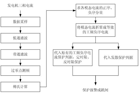
[0062] The invention designs a method capable of detecting sub-synchronous currents in multiple modes in the generator armature current, and realizing the overcurrent protection and divergence protection of the sub-synchronous currents. The specific implementation of the method will be described below in conjunction with the specific situation of a 600MW turbo generator in a certain power plant.

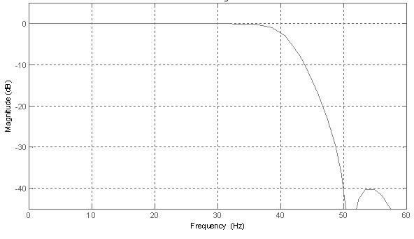
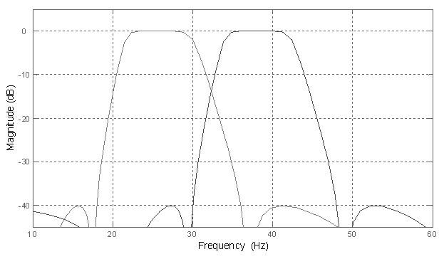
[0063] The generator set is equipped with a static blocking filter SBF on the high voltage side of the main transformer, and the SBF is a circuit in which some inductors and capacitors are connected in series and parallel. The field test shows that after the SBF is put into use, the generator has asynchronous self-excitation phenomenon, and the three-phase current of the generator contains these two sub-synchronous modal components with frequencies near 27.0Hz and 39.0Hz; stimulated to a certain extent. In order to prevent asynchronous self-excited oscillation from damaging the gene...


PUM


Abstract

The invention discloses a method for sub-synchronous current calculation and sub-synchronous over-current and divergent protection of a generator. The method comprises the following steps of: acquiring the three-phase current signals of the generator, converting positive and negative sequence components of various modal sub-synchronous currents of the current into equivalent power-frequency negative sequence currents via the following formula, substituting the results into the original power-frequency negative sequence over-current protection criteria of the generator and then making fixed time-lag and reverse time-lag protection judgments; and judging if the equivalent power-frequency negative sequence over-current increases continuously and forming an divergent protection criteria. When the method is used, multi-modal sub-synchronous currents in the current of the generator armature can be detected, and the over-current protection and divergent protection of the sub-synchronous currents can be realized. Particularly, many sets of signals with sub-synchronous modal frequencies are separated by low-pass filtering and bandpass filtering; the sub-synchronous modal frequencies can be obtained by zero crossing point algorithm, and the amplitude sequence and phasor of the modal signals are obtained by Fourier calculation. The method can be applied in the original power-frequency negative sequence current protection of the generator, the formats and constant values of the protection criteria are unchanged.

Description

technical field [0001] The present invention relates to the technical field of generator protection in power systems, more specifically to subsynchronous oscillation of turbogenerators, and to subsynchronous current detection, overcurrent protection, divergence protection methods and corresponding relays in generator armature currents protective or monitoring devices. Background technique [0002] Some large-scale thermal power plants are far away from the load center, and the capacity of the generator set is large, so long-distance power transmission is mostly used, and power electronic equipment such as series capacitor compensation and controllable series capacitor compensation are installed in the transmission line, and DC transmission is sometimes used. When the parameters of these units are compensated by capacitance or long-distance lines with no load, asynchronous self-excitation (abbreviated as asynchronous self-excitation) may occur, and the armature current in the...

Claims


Application Information

Patent Timeline
Patent Type & Authority Applications(China)
IPC IPC(8): H02H7/09
CPCG01R31/42G01R31/343
Inventor 张琦雪牛红海柏传军熊良根王凯陈俊严伟
Owner NR ELECTRIC CO LTD
Why Eureka
Try Eureka