Cutting tools

A technology for cutting tools and cutting parts, which is applied in the field of portable cutting tools, can solve problems such as difficulty in applying force, and achieve the effects of easy grip, improved operating performance, and good balance

Inactive Publication Date: 2011-09-21
MAKITA CORP
View PDF5 Cites 5 Cited by
  • Summary
  • Abstract
  • Description
  • Claims
  • Application Information

AI Technical Summary

Problems solved by technology

[0007] However, the existing rod-shaped handle extends straight from the tool body to the rear side, so it is difficult for the user to apply force to the cutting direction when grasping it.

Method used


Image

  • Cutting tools
  • Cutting tools
  • Cutting tools

Examples


Embodiment Construction

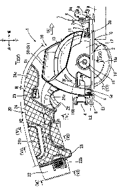
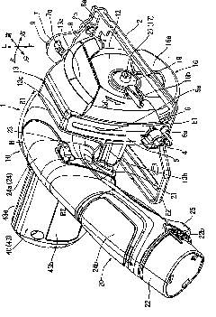
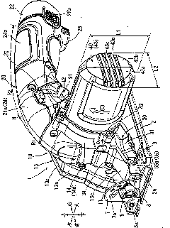
[0102] Next refer to Figure 1-20 A specific embodiment of the present invention will be described. Figure 1~4 Shown is an overall view of the portable cutting tool 1 of this embodiment. The cutting tool 1 is called a portable circular saw, and is a relatively small and light cutting machine. The user can hold the cutting tool 1 and move it on the workpiece W to perform cutting. Firstly, its overall structure will be roughly explained below.

[0103] This cutting tool 1 has a plate-shaped base 2 for being placed on the upper surface of a workpiece W to be cut, and a tool body 10 is supported on the upper surface of the base 2 . exist figure 1 , the user is located on the left side of the cutting tool 1, by turning the cutting tool 1 to figure 1 middle right ( figure 1 The direction shown by the hollow arrow (A)) moves to enable cutting. In the following description, unless otherwise specified, as shown in each figure, the direction in which the cutting process is perfor...


PUM


Abstract

On a cutting tool generally named as a portable circular saw, a conventional handle part is in a rod shape perpendicularly backwards extending, it is necessary to keep a wrist in a constrained posture, because the rod-shaped handle at the using end can be freely grasped and the operation can be easily applied on the handle. The handle (20) is viewed to be a mountain form bending upwards from the side surface and the highest part (H) of the handle is at the front position and the downward extending region from the highest part (H) to the rear end bends upwards in a curvature samller than that of the highest part (H).

Description

technical field [0001] The present invention relates to a portable cutting tool, for example known as a portable circular saw. Background technique [0002] This cutting tool has a structure in which a tool body is supported on an upper surface of a base placed on a workpiece to be cut, and the tool body has a circular rotary cutter driven by an electric motor to rotate. When cutting, the lower part of the rotary cutter protruding to the side of the lower surface of the base cuts into the workpiece while moving the tool body in the direction of cutting progress so that the cutting process can be performed. Therefore, a handle portion is provided on the tool body for the user to grasp so as to operate the tool body to move in the cutting direction. [0003] As the handle part, in addition to the ring-shaped (endless type), for example, as disclosed in the following patent documents, there is also a rod-shaped one with an end (the rear end is a free end). In contrast, when t...

Claims


Application Information

Patent Timeline
Patent Type & Authority Applications(China)
IPC IPC(8): B23D45/16B25F5/02
CPCB27B9/00B25F5/008B25F5/02Y10T83/7872
Inventor 稻吉广共
Owner MAKITA CORP
Why Eureka
Try Eureka