Oil pressure control apparatus

A technology for controlling device and oil pressure, which is applied to valve devices, controlling lubricant pressure, mechanical equipment, etc., can solve the problems of increasing manufacturing costs and achieve the effect of simple control

Inactive Publication Date: 2011-09-28
AISIN SEIKI KK
View PDF6 Cites 31 Cited by
  • Summary
  • Abstract
  • Description
  • Claims
  • Application Information

AI Technical Summary

Problems solved by technology

Accordingly, if the oil pressure control device disclosed in Patent Document 1 is actually installed in a vehicle, the manufacturing cost will increase.

Method used


Image

  • Oil pressure control apparatus
  • Oil pressure control apparatus
  • Oil pressure control apparatus

Examples


Embodiment Construction

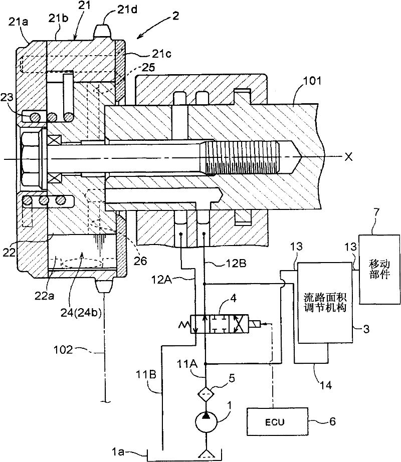
[0043] Next, an embodiment of an oil pressure control device applicable to an engine oil pressure control device for a vehicle engine will be described with reference to the accompanying drawings. According to the present embodiment, the valve timing control device provided at the intake valve serves as the control device.

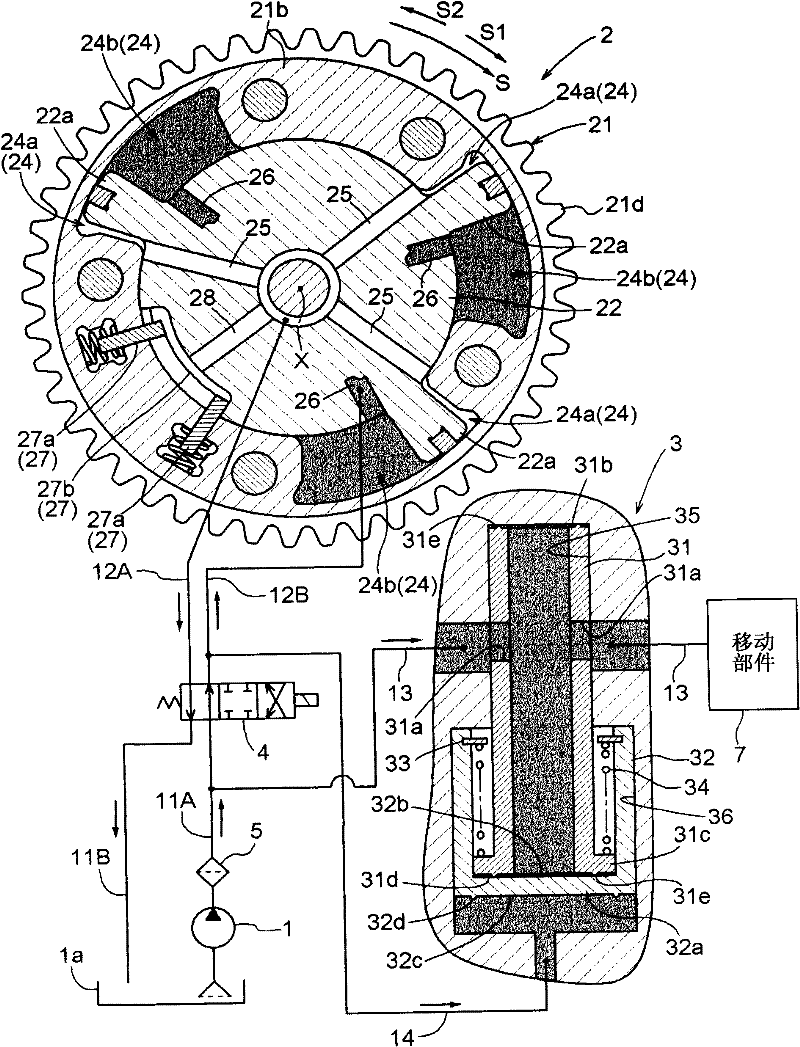
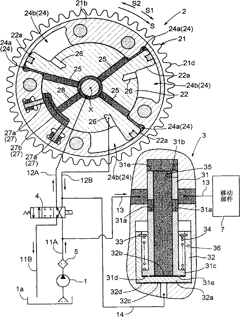
[0044] Such as figure 1 As shown, the engine oil pressure control device includes: a pump 1, which is driven by the rotation of the engine; a valve timing control device (VVT) 2 as a control device, which rotates the driven side rotating member relative to the driving side by supplying or discharging oil. and an oil control valve (OCV) 4 as a control valve mechanism for controlling the supply of oil to the valve timing control device 2 and the discharge of oil from the valve timing control device 2 . The pump 1 is connected to the OCV 4 via a discharge flow path 11A as a first flow path. The valve timing control device 2 is connected to the OCV 4 via a r...


PUM


Abstract

An oil pressure control apparatus includes a control valve mechanism (4) being in communication with a pump (1) via a first fluid passage (11A) and being in communication with a control apparatus (2) via a second fluid passage (12B), a third fluid passage (13) diverging from the first fluid passage to supply oil to a predetermined portion (7) other than the control apparatus, and a fluid passage dimension regulating mechanism (3) including a movable member (31) provided at the third fluid passage and including an opening (31 a) for regulating a fluid passage dimension of the third fluid passage. The fluid passage dimension regulating mechanism is in communication with a fourth fluid passage (14) diverging from the second fluid passage and biases the movable member to a side increasing the fluid passage dimension by applying the hydraulic pressure of the fourth fluid passage to the movable member separately from the hydraulic pressure of the third fluid passage.

Description

technical field [0001] The invention relates to a machine oil pressure control device. Background technique [0002] A known oil pressure control device is disclosed in JP2009-299573A (hereinafter referred to as Patent Document 1). The engine oil pressure control device disclosed in Patent Document 1 includes a control device (ie, a valve timing control device) and an engine lubricating device. The control device includes a pump driven by the rotation of the engine to discharge engine oil (that is, an oil pump), a driving side rotating member (that is, an outer rotor) that rotates synchronously with the crankshaft, and a drive side rotating member that is coaxially arranged to synchronize with the camshaft. The rotating driven side rotating member (that is: the inner rotor), and the control device changes the relative rotational phase of the driven side rotating member relative to the driving side rotating member by supplying and discharging oil, thereby controlling the tim...

Claims


Application Information

Patent Timeline
Patent Type & Authority Applications(China)
IPC IPC(8): F01M1/16
CPCF01L2001/34473F01L1/3442F01L2001/34423F01L2001/34476F01M1/16F01L2001/34466F01L2001/34459
Inventor 宫地永治小泽保夫
Owner AISIN SEIKI KK
Why Eureka
Try Eureka