Dual mode depth imaging

A depth image, depth technology, applied in the field of dual-mode depth imaging, can solve the problem of distance can not be distinguished

Active Publication Date: 2011-09-28
MICROSOFT TECH LICENSING LLC
View PDF7 Cites 25 Cited by
  • Summary
  • Abstract
  • Description
  • Claims
  • Application Information

AI Technical Summary

Problems solved by technology

In this method, distances to objects that differ ...

Method used


Image

  • Dual mode depth imaging
  • Dual mode depth imaging
  • Dual mode depth imaging

Examples


Embodiment Construction

[0023] In the following detailed description, numerous specific details are set forth in order to provide a thorough understanding of the present invention. However, it will be understood by those skilled in the art that the present invention may be practiced without these specific details. In other instances, well-known methods, procedures, and components have not been described in order not to obscure the present invention.

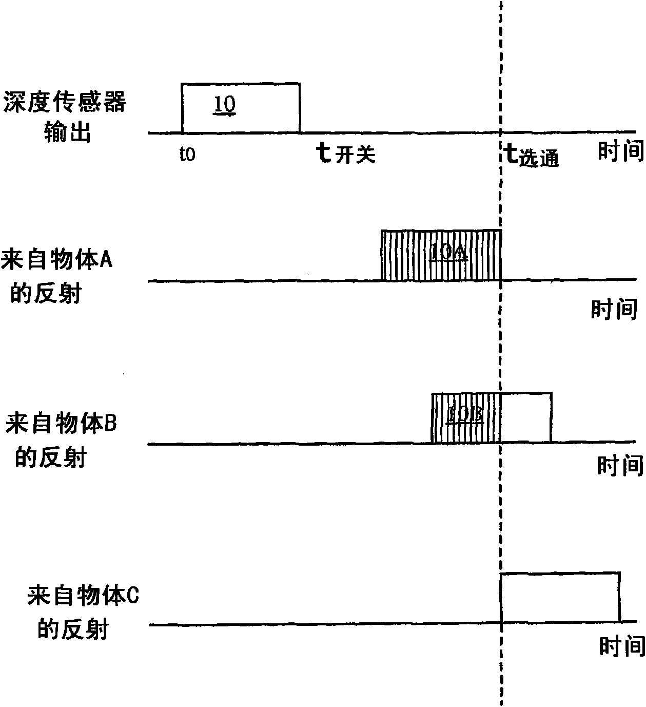
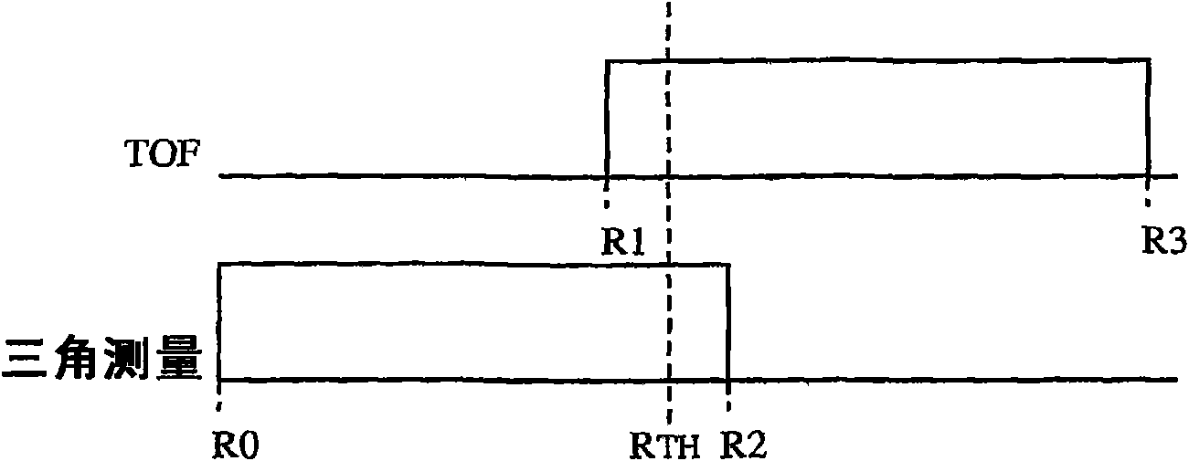
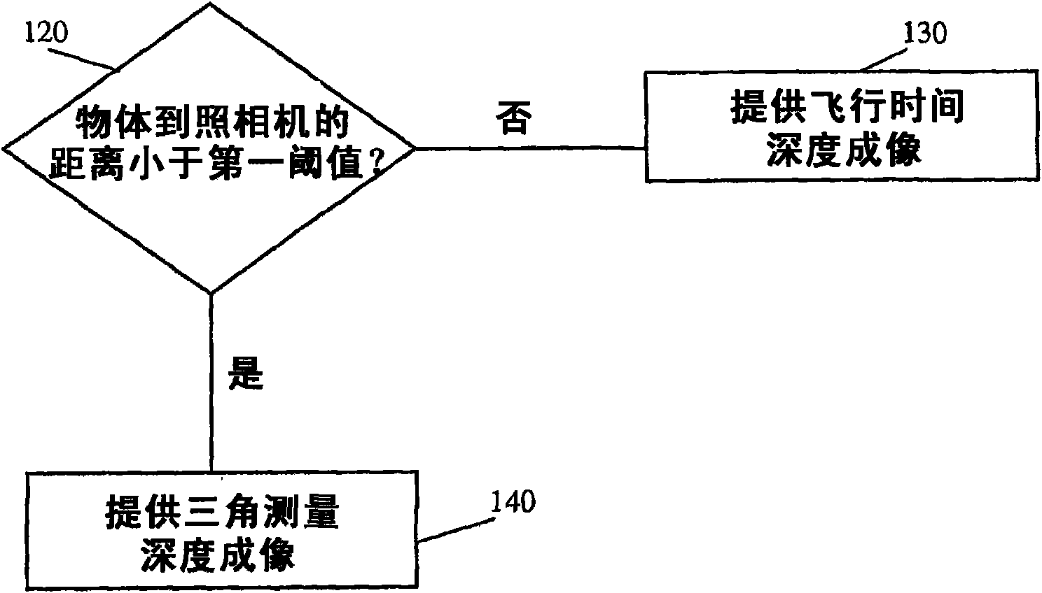
[0024] Depth imaging by triangulation may not be suitable when real-time and continuous imaging is required. For example, in passive triangulation, several means of image matching may be used in order to ensure that the spatial angle data from both cameras relate to the same point on the object. The image matching process and triangulation calculations may be significantly lengthened. In active triangulation, objects may need to be scanned angle by angle, which can make the process lengthy and complicated. Depth imaging measured by TOF using frequent...


PUM


Abstract

A depth imaging system comprising: apparatus operable in first and second modes to provide depth images of a scene; and a processor adapted to selectively control the apparatus to operate in the first or second mode to provide a depth map responsive to at least one predefined threshold.

Description

[0001] related application [0002] Pursuant to 35 U.S.C. 120, this application claims the benefit of US Patent Application 11 / 984,250, filed November 15, 2007, the contents of which are hereby incorporated by reference. Background technique [0003] There are two main methods for generating 3D images. One method uses triangulation. Another method is based on time-of-flight measurements. [0004] Triangulation is any kind of distance operation based on a given length and angle using triangular relations. [0005] Triangulation with two parallel cameras, or stereo triangulation, can be based on, for example, the distance between the cameras, the focal length of the cameras, the spatial angle of the line of sight (LOS) from the object being imaged to each camera, and / or other suitable parameters, etc. parameters to execute. This type of triangulation is sometimes called "passive triangulation". Such triangulation may require additional means to determine which points in the...

Claims


Application Information

Patent Timeline
IPC IPC(8): H04N13/00H04N13/239
CPCG01S17/023G01S17/89H04N13/0239H04N13/0207H04N13/0253G01S17/87G01S17/48H04N13/254H04N13/207H04N13/239G01S17/86G01S17/894
Inventor G·叶海弗
Owner MICROSOFT TECH LICENSING LLC
Why Eureka
Try Eureka