Dual mode touch system

a touch system and dual-mode technology, applied in the field of user input systems, can solve the problems of high hardware cost of the touch system, increase the cost of manufacture, and translate into high resolution

Inactive Publication Date: 2005-11-03
PIXART IMAGING INC
View PDF25 Cites 172 Cited by
  • Summary
  • Abstract
  • Description
  • Claims
  • Application Information

AI Technical Summary

Benefits of technology

[0024] The present invention provides advantages in that the imaging device is able to see pointer contacts on the touch surface even in situations where the user rests his forearm and/or han...

Problems solved by technology

Although the above touch system works extremely well, the use of four digital cameras and associated digital signal processors to capture and process images makes the touch system hardware-intensive and therefore, increases the costs of manufacture.
This of course translates into higher costs to consumers.
Although the ...

Method used


Image

  • Dual mode touch system
  • Dual mode touch system
  • Dual mode touch system

Examples


Embodiment Construction

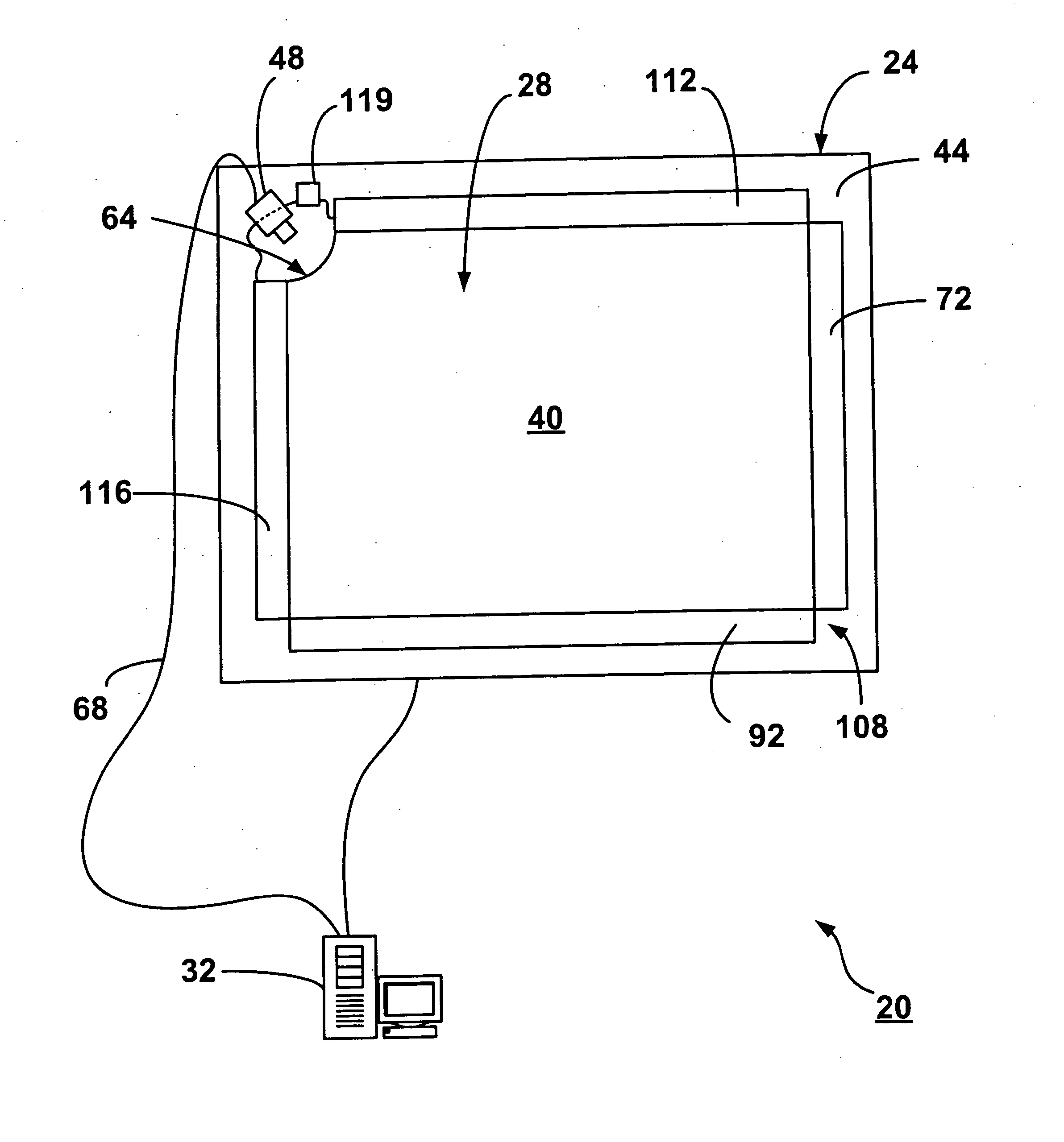
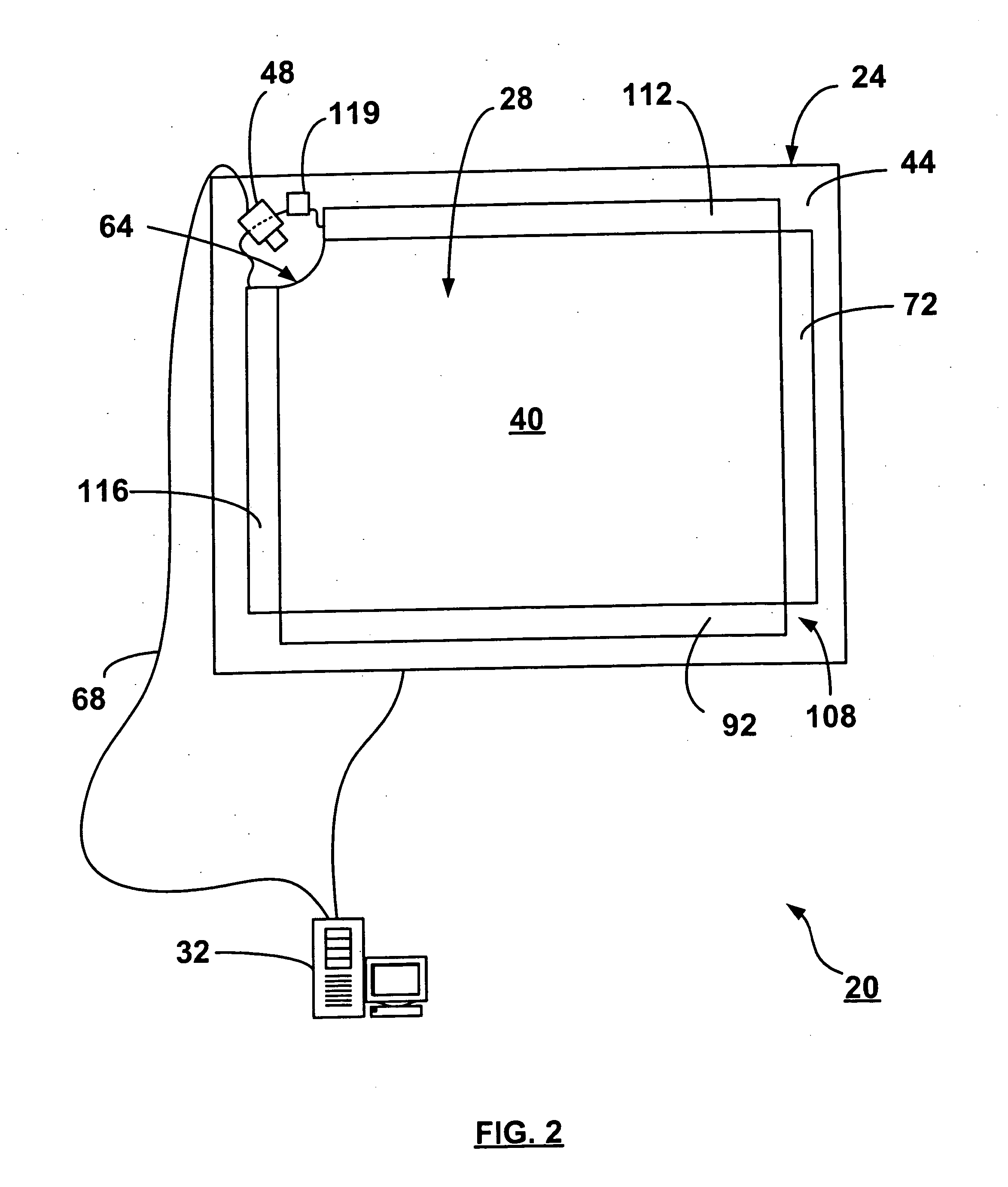
[0044] Turning now to FIG. 2, an apparatus for detecting a pointer within a region of interest is shown and is generally identified by reference numeral 20. In this particular embodiment, apparatus 20 is in the form of a touch system. The touch system 20 includes a generally rectangular touch panel assembly 24 encompassing the region of interest. Touch panel assembly 24 includes a generally transparent touch panel 28 that overlies the display screen of a display unit such as for example, a flat-panel monitor or the like (not shown) and an imaging device 48 that is positioned adjacent one corner of the touch panel 28. The imaging device 48 looks both across and through the touch panel 28 and acquires images within its field of view. The acquired images are processed by the imaging device 48 to determine whether a pointer exists in the captured images and if so, to determine the location of the pointer relative to the touch panel 28. Pointer location data generated by the imaging devi...


PUM


Abstract

An apparatus for detecting a pointer includes a waveguide and a touch surface over the waveguide on which pointer contacts are to be made. At least one reflecting device extends along a first side of the waveguide and touch surface. The reflecting device defines an optical path between the interior of the waveguide and the region of interest above the touch surface. At least one imaging device looks across the touch surface and into the waveguide. The imaging device captures images of the region of interest and within the waveguide including reflections from the reflecting device.

Description

FIELD OF THE INVENTION [0001] The present invention relates generally to user input systems and in particular to an apparatus for detecting a pointer within a region of interest. BACKGROUND OF THE INVENTION [0002] Touch systems are well known in the art and typically include a panel having a touch surface on which contacts are made using a pointer in order to generate user input. Pointer contacts with the touch surface are detected and are used to generate corresponding output depending on areas of the touch surface where the contacts are made. There are basically two general types of touch systems available and they can be broadly classified as “active” touch systems and “passive” touch systems. [0003] Active touch systems allow a user to generate user input by contacting the touch surface with a special pointer that usually requires some form of on-board power source, typically batteries. The special pointer emits signals such as infrared light, visible light, ultrasonic frequenci...

Claims


Application Information

Patent Timeline
IPC IPC(8): G06F3/033G06F3/042G09G5/00
CPCG06F3/03545G06F3/042G06F3/0421
Inventor UNG, CHI MAN CHARLESBOOTH, DAVID KENNETHSIROTICH, ROBERTO A. L.
Owner PIXART IMAGING INC
Why Eureka
Try Eureka