
Dual mode hemodialysis machine

a hemodialysis machine and dual-mode technology, applied in the field of hemodialysis machines, can solve the problems of large disruption to work and family life, large disruption to travel plans, and the bulky bulk of conventional single-pass hemodialysis machines,

Inactive Publication Date: 2011-11-10
C TECH BIOMEDICAL
View PDF12 Cites 165 Cited by
  • Summary
  • Abstract
  • Description
  • Claims
  • Application Information

AI Technical Summary

Benefits of technology

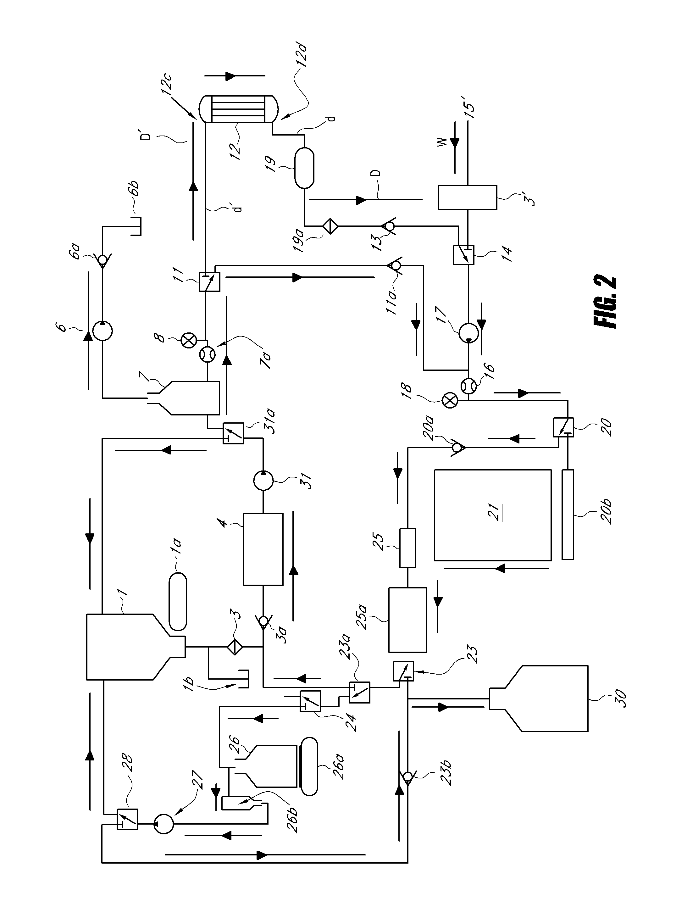
"The patent describes a small and portable hemodialysis machine system that can switch between two modes: sorbent dialysis and single-pass dialysis. The system includes a sorbent cartridge to purify the dialysate fluid, an acetate pump, a bicarbonate pump, and a mixing chamber to create the dialysate. The system also has a reverse osmosis device to provide water, and a drain to collect used dialysate. The system can switch between modes easily to provide flexibility for patients and healthcare professionals."

Problems solved by technology

Conventional single-pass hemodialysis machines are bulky and difficult to handle by medical personnel who operate the machines to conduct dialysis treatments on patients.
Patients who visit such clinics or hospitals for dialysis treatments can spend up to 6 hours at such facilities per treatment, which is a great source of inconvenience for busy individuals and can cause great disruptions to work and family life, as well as travel plans.
Because of the need for a dedicated water source and their bulkiness and cost, such single-pass machines are not mobile and generally in a fixed location within the hospital or dialysis clinic.
Existing sorbent hemodialysis machines, though they are generally portable and to not need a dedicated water source, suffer from several deficiencies.
One such deficiency is the low dialysate flows provided by the sorbent hemodialysis machines.
Such lower flows require patients to undertake more frequent treatments, not all of which may be fully reimbursable.
Therefore, in addition to the added inconvenience of needing more frequent dialysis treatments, conventional sorbent hemodialysis machines can result in added expense to the patient.

Method used


Image

  • Dual mode hemodialysis machine
  • Dual mode hemodialysis machine
  • Dual mode hemodialysis machine

Examples


Embodiment Construction

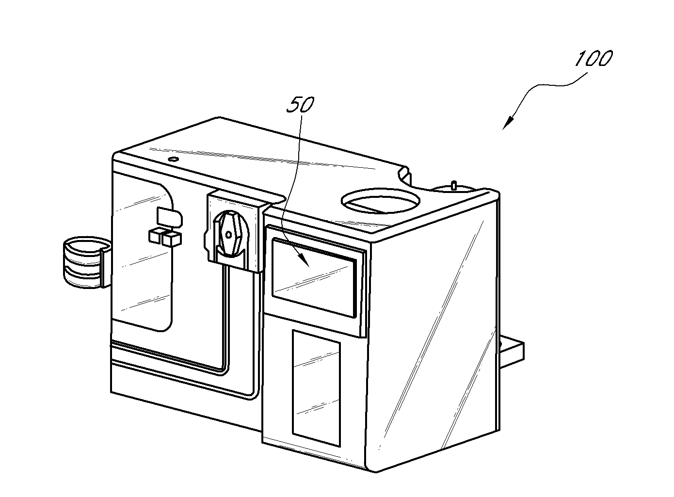
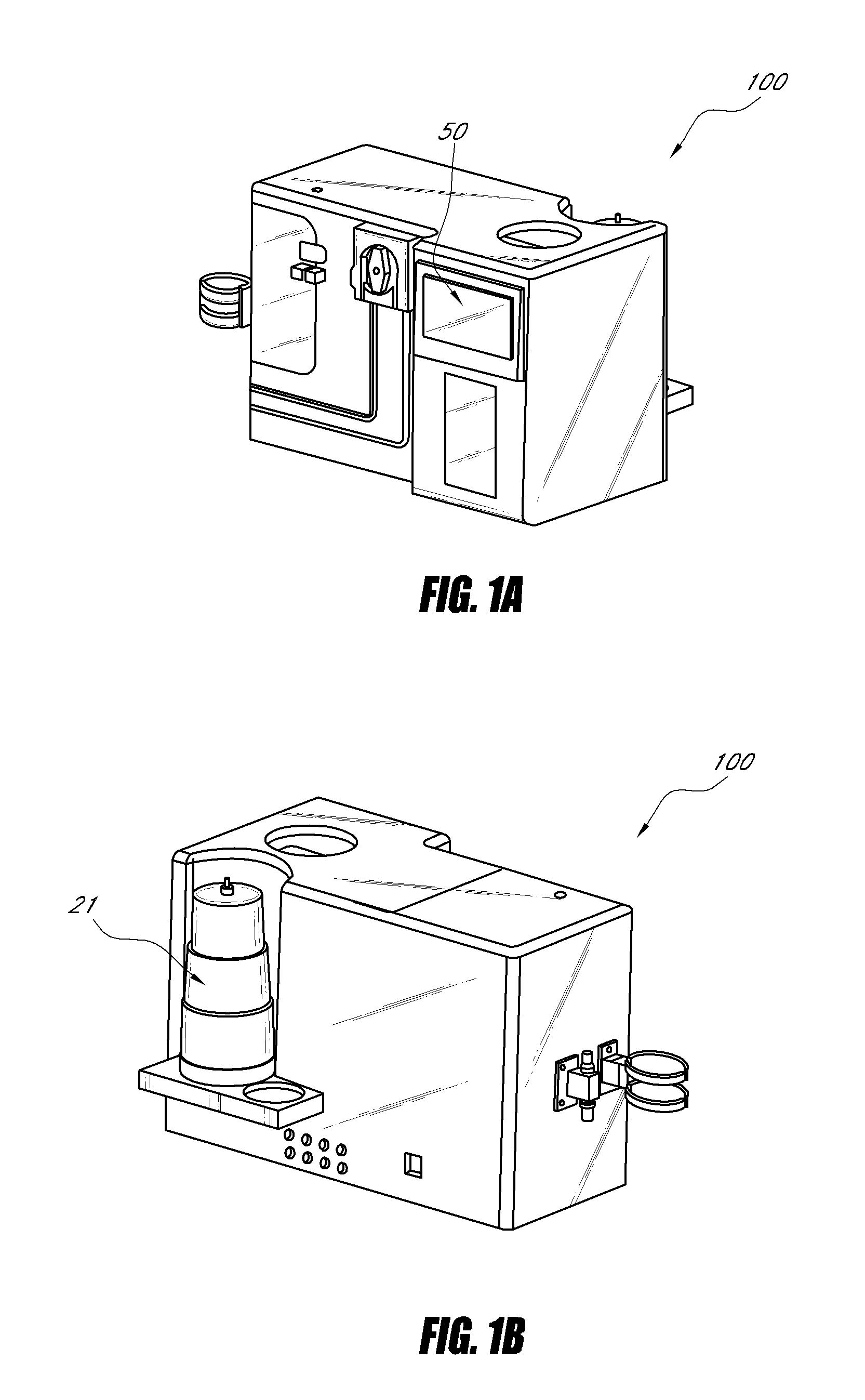
[0022]FIGS. 1A and 1B show one embodiment of a dual mode hemodialysis machine 100. In one embodiment, the machine 100 is generally rectangular in shape and can have a length L, height H and depth D of about 2 feet by about 1 foot by about 1 foot. In another embodiment, the machine 100 can have dimensions of about 23 inches by about 12 inches by about 15 inches. In still another embodiment, the machine 100 can have length, width and depth dimensions of about 23 inches by 11 inches by 14 inches. In one embodiment, the machine 100 can advantageously weigh 60 lbs or less. In another embodiment, the machine 100 can weigh 50 lbs or less. In still another embodiment, the machine can weigh about 45 lbs.

[0023]With continued reference to FIGS. 1A and 1B, the dual mode hemodialysis machine 100 can include a sorbent cartridge 21 removably coupleable to a base of the machine 100. The machine 100 can also have a screen 50, such as a digital video screen, for displaying various parameters of the o...


PUM


Abstract

A compact portable dual mode hemodialysis machine system is provided. The system includes a sorbent dialysis module with a sorbent cartridge that purifies a dialysate fluid that flows therethrough, where the sorbent dialysis module returns the purified dialysate fluid from the sorbent cartridge to an inlet of a dialyzer. The system also includes a single-pass dialysis module with an acetate pump, a bicarbonate pump and a mixing chamber, where the acetate and bicarbonate pumps flow acetate and bicarbonate mixtures, respectively, into the mixing chamber. The single-pass dialysis module receives a desired amount of water from a reverse osmosis device, the single-pass dialysis module operated to direct used dialysate from the dialyzer to a drain. The machine system can be operated to replace the sorbent cartridge with the single-pass dialysis module to switch the operation of the dual mode hemodialysis machine system from a sorbent dialysis mode to a single-pass dialysis mode

Description

CROSS-REFERENCE TO RELATED APPLICATIONS[0001]This application claims the benefit of U.S. Provisional Patent Application No. 61 / 331,273 filed May 4, 2010, the entire contents of which are incorporated herein by reference and should be considered a part of this specificationBACKGROUND[0002]1. Field[0003]The present invention is directed to hemodialysis machines, and more specifically to a dual mode portable hemodialysis machine.[0004]2. Description of the Related Art[0005]Conventional single-pass hemodialysis machines are bulky and difficult to handle by medical personnel who operate the machines to conduct dialysis treatments on patients. Additionally, such single-pass machines require a dedicated source of water, and water treatment system, and so are generally used in hospitals and dialysis clinics. Patients who visit such clinics or hospitals for dialysis treatments can spend up to 6 hours at such facilities per treatment, which is a great source of inconvenience for busy individu...

Claims


Application Information

Patent Timeline
Patent Type & Authority Applications(United States)
IPC IPC(8): A61M1/34
CPCA61M1/1656A61M1/3646A61M1/287A61M1/1696A61M1/1668
Inventor PALMER, GRANT
Owner C TECH BIOMEDICAL
Learn More