System for measuring vital signs during hemodialysis

a vital sign and monitoring system technology, applied in the field of blood pressure monitoring, can solve the problems of increasing or reducing the patient's heart rate, increasing the body temperature of the patient, and reducing the patient's blood pressure quickly, so as to simplify and expedite the application of the monitor to the patien

Active Publication Date: 2011-03-17
SOTERA WIRELESS
View PDF5 Cites 108 Cited by
  • Summary
  • Abstract
  • Description
  • Claims
  • Application Information

AI Technical Summary

Benefits of technology

[0020]In embodiments, the finger-worn sensor includes the first electrode. This simplifies and expedites application of the monitor to the patient. Typically the electrode is a conductive metal electrode that is not disposable. In other embodiments the cuff-based system includes a second processing module configured to process the pressure waveform to determine values for SYS, DIA, and MAP. Here, the cuff-based system includes a cable that plugs into the processing module within the body-worn monitor to supply the pressure waveform and blood pressure values.

Problems solved by technology

Rapid extraction of fluid can cause the patient's blood pressure to quickly decrease due to the lack of volume in the vessels.
This can also increase or reduce the patient's heart rate, increase their body temperature, and induce nausea and severe fatigue.
In some cases these side effects can be life-threatening.

Method used


Image

  • System for measuring vital signs during hemodialysis
  • System for measuring vital signs during hemodialysis
  • System for measuring vital signs during hemodialysis

Examples


Embodiment Construction

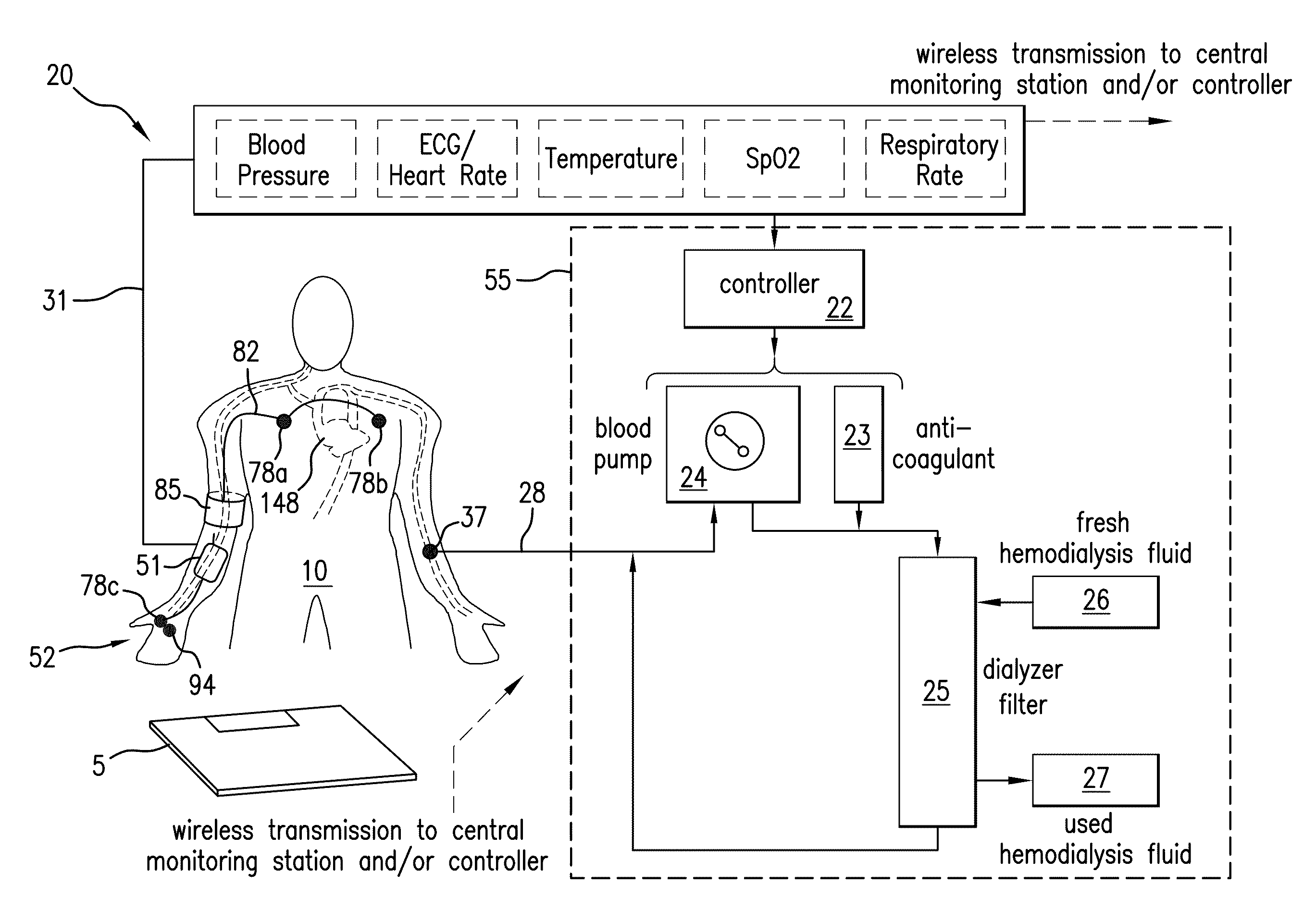
[0041]FIG. 1 shows a schematic drawing of a system 20 for continuously monitoring vital signs, and particularly blood pressure, from a patient 10 attached to a hemodialysis machine 55. The system 20 features a body-worn monitor 51 that uses the Composite Method to measure SYS, DIA and other vital signs (e.g. heart rate, temperature, SpO2, and respiratory rate) and time-dependent waveforms (e.g. ECG, PPG). The body-worn monitor 51 connects to a cuff-based monitor 85 featuring an embedded, inflatable bladder that connects to a cuff-based pneumatic system (described below). During an indexing measurement the cuff-based monitor 85 attaches proximal to the patient's brachial artery. The body-worn monitor 51 additionally connects to a finger-worn sensor 94 featuring a cable terminated with an end portion 52 that typically wraps around the base of the patient's thumb. The end portion 52 includes one or more electrodes 78c and an optical sensor, typically with multiple light-emitting diodes...


PUM


Abstract

The invention provides a system for continuously monitoring a patient during hemodialysis. The system includes a hemodialysis machine for performing the hemodialysis process that features a controller, a pump, a dialyzer filter, a lumen, and an interface to a body-worn monitor. A patient attaches to the dialysis machine through the lumen, and wears a body-worn monitor for continuously measuring blood pressure. The monitor includes an optical system for measuring an optical waveform, an electrical system for measuring an electrical waveform, and a processing component for determining a transit time between the optical and electrical waveforms and then calculating a blood pressure value from the transit time. The body-worn monitor features an interface (e.g. a wired serial interface, or a wireless interface) to transmit the blood pressure value to the controller within the hemodialysis machine. The controller is configured to receive the blood pressure value, analyze it, and in response adjust the dialysis process.

Description

CROSS REFERENCES TO RELATED APPLICATIONS[0001]Not ApplicableSTATEMENT REGARDING FEDERALLY SPONSORED RESEARCH OR DEVELOPMENT[0002]Not ApplicableBACKGROUND OF THE INVENTION[0003]1. Field of the Invention[0004]This invention relates to systems for monitoring vital signs, and particularly blood pressure, during hemodialysis.[0005]2. Description of the Related Art[0006]Patents in late-stage renal failure typically require hemodialysis for survival. During a hemodialysis treatment, blood is extracted from a patient's veins to remove excess water and waste products, such as potassium and uric acid, with a process that combines diffusive clearance across a membrane (dialysis) and convective clearance (ultrafiltration). Rapid extraction of fluid can cause the patient's blood pressure to quickly decrease due to the lack of volume in the vessels. This can also increase or reduce the patient's heart rate, increase their body temperature, and induce nausea and severe fatigue. In some cases these...

Claims


Application Information

Patent Timeline
Patent Type & Authority Applications(United States)
IPC IPC(8): A61B5/00
CPCA61B5/0205A61M2230/50A61B5/02225A61B5/02233A61B5/02438A61B5/0816A61B5/14551A61B5/6826A61B5/6838A61M1/14A61M1/30A61M2205/3306A61M2205/3576A61M2209/088A61M2230/04A61M2230/30A61M2230/42A61B5/022A61M2205/50A61M2205/502
Inventor BANET, MATTKING, ANDREW JAMES
Owner SOTERA WIRELESS
Why Eureka
Try Eureka