
Multi-channel biological signal telemetry systems

a biological signal and telemetry technology, applied in the field of multi-channel biological signal telemetry system, can solve the problems of large current consumption of general transceivers, difficult to determine s/n ratio and sample electroencephalogram data,

Active Publication Date: 2005-04-21
NIHON KOHDEN CORP
View PDF17 Cites 117 Cited by
  • Summary
  • Abstract
  • Description
  • Claims
  • Application Information

AI Technical Summary

Benefits of technology

[0012] It is therefore an object of the invention to provide a multi-channel biological signal telemetry system which enables continuous, long-term measurement of multi-channel biological signal information even when a patient on the move carries a biological signal information transmitter.
[0013] It is also an object of the invention to provide a multi-channel biological signal telemetry system capable of increasing the amount of information by multi-channeling electroencephalogram data, and enabling continuous measurement over a long time period, in order to realize simple, flexible and accurate analysis in connection with monitoring of expression of pathological signs of diseases such as epilepsy or polysomnography (hereinafter referred to as “PSG”) testing or the like, thereby enabling effective detection of a part of the brain causing epileptic episodes, abnormal electroencephalograms, or the like, and treatment thereof.
[0022] With the above configuration, power consumption of the battery for the first transceiver can be suppressed. Accordingly, there is enabled continuous, long-term measurement of multi-channel biological signal information in an unconstrained manner, which has been conventionally considered to be difficult, and flexible and more accurate analysis and diagnosis can be conducted in a simple and convenient manner for monitoring, examining, and the like expression of various pathological signs of diseases. As a result, discovery of a disease and treatment thereof can be effectively attained.
[0027] In this case, flexible and accurate analysis and diagnosis can be conducted in a simple and convenient manner in connection with PSG testing, monitoring of expression of various pathological signs of diseases such as epilepsy, or the like.
[0029] In this case, since a transmission speed of the digital data by way of wireless transmission is increased, a period until completion of the data transmission is shortened. Accordingly, a time period during which the battery for the transceiver is activated can be further shortened while prolonging a time period during which the battery is deactivated, whereby the operable time of the battery is prolonged.

Problems solved by technology

Because human electroencephalograms are very feeble electrical signals and include random waveforms called brain noise, difficulty is encountered in determining an S / N ratio and sampling electroencephalogram data.
Accordingly, great difficulty is encountered in transmitting electroencephalogram data, which require high resolution and high sampling per channel, on 32 channels or more.
Further, a general transceiver consumes a considerable amount of current, regardless of an operating state, only when the power of the transceiver is active.
For instance, long-term operation of 24 hours or longer is highly difficult.
As described above, a system configuration of a related-art electroencephalogram telemetry apparatus has failed to implement a portable multi-channel electroencephalogram telemetry system of 32 channels or more capable of performing battery-powered operation for 24 hours or longer.

Method used


Image

  • Multi-channel biological signal telemetry systems
  • Multi-channel biological signal telemetry systems
  • Multi-channel biological signal telemetry systems

Examples


Embodiment Construction

[0035] Embodiments of a multi-channel biological signal telemetry system according to the present invention will be described hereinbelow in detail by reference to the accompanying drawings.

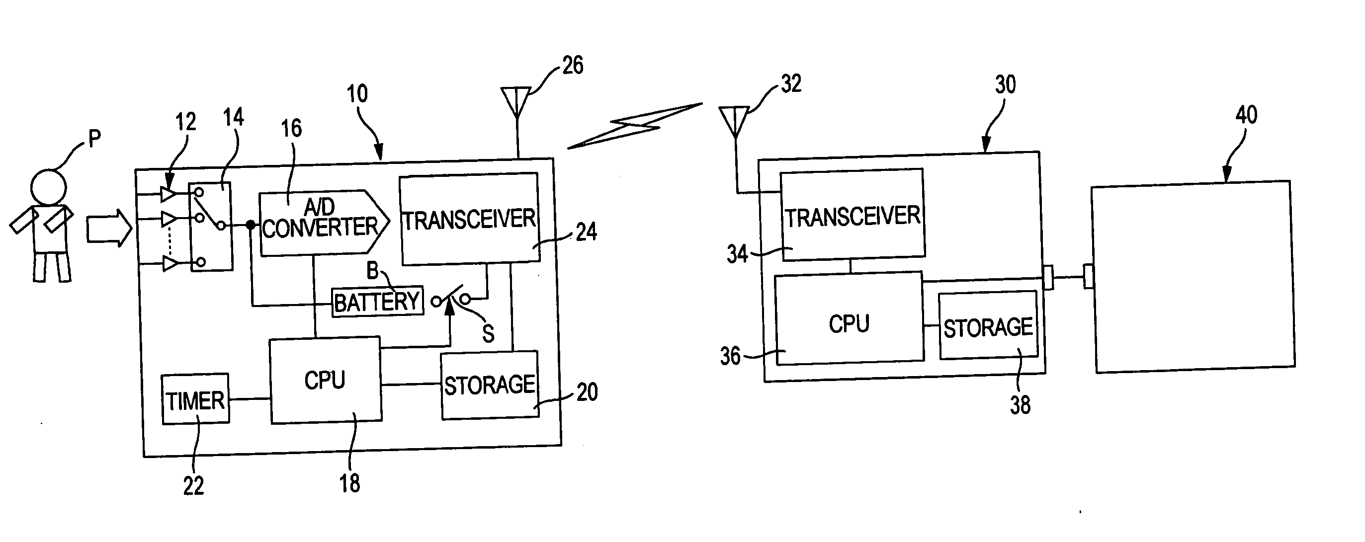
[0036]FIG. 1 shows a multi-channel electroencephalogram telemetry system according to one embodiment of the multi-channel biological signal telemetry system of the invention. The multi-channel electroencephalogram telemetry system comprises a transmitter 10, a receiver 30, and an electroencephalograph 40.

[0037] The transmitter 10 comprises a multi-channel amplifier 12, a multiplexer 14, an A / D converter 16, a CPU 18, a storage 20, a timer 22, a transceiver 24, an antenna 26, a battery B for activating the transceiver 24, and a switch S which switches between activation and deactivation of the battery B. The multi-channel amplifier 12 amplifies respective electroencephalogram signals detected from a plurality of electrodes (unillustrated) attached on a head of a patient P upon input thereof.

[00...


PUM


Abstract

A system for performing telemetry of multi-channel biological signals obtained from electrodes attached to a subject, is provided with a transmitter and a receiver. In the transmitter, a converter converts the multi-channel biological signals to digital data, and a storage stores the digital data. In the transmitter, a first transceiver is operable to transmit a prescribed amount of the digital data stored in the storage, and a battery is operable to supply a battery voltage to the first transceiver. In the transmitter, a switch places the battery in either a first state where the battery voltage is supplied to the first transceiver or a second state where the battery voltage is not supplied to the first transceiver, so that the first transceiver intermittently transmits the digital data. In the receiver, a second transceiver is operable to receive the digital data transmitted from the first transceiver. The received digital data is to be reproduced multi-channel biological signals at an output device.

Description

BACKGROUND OF THE INVENTION [0001] The present invention relates to a multi-channel biological signal telemetry system for measuring or monitoring biological signals, such as electroencephalograms, which are led from a human scalp or the surface of the cerebral cortex as feeble potential variations (of several to hundreds of μV) having frequency components superposed thereon, an electrocardiogram, an electromyogram, respiratory waveforms, SpO2, or the like. [0002] Since the physical and / or mental state of a person can be determined by frequencies of electroencephalograms obtained by the person, a system for controlling equipment, such as a reclining apparatus, by utilization of electroencephalograms has hitherto been developed. For instance, Japanese Patent Publication No. 8-71050A discloses a system capable of creating a comfortable environment by controlling an equipment on the basis of not only information about electroencephalograms sampled at the present time, but also the diff...

Claims


Application Information

Patent Timeline
Patent Type & Authority Applications(United States)
IPC IPC(8): A61B5/00A61B5/04A61B5/0476A61N1/08
CPCA61B5/0006Y10S128/903A61N1/08
Inventor YANAGIHARA, KAZUTERUISHIKAWA, TAKAHISAIMAJO, KAORU
Owner NIHON KOHDEN CORP
Learn More