
Method and apparatus for detecting objects

a technology for objects and detection methods, applied in the field of object detection, can solve the problems of significant changes in ambient lighting conditions, many existing object detection systems, including those that use change detection algorithms to detect objects, can be challenged, etc., and achieve the effect of less effect on the efficacy of the object detection system and high effectiveness

Inactive Publication Date: 2005-01-11
HONEYWELL INT INC
View PDF114 Cites 112 Cited by
  • Summary
  • Abstract
  • Description
  • Claims
  • Application Information

AI Technical Summary

Benefits of technology

In another illustrative embodiment, a moiré interference pattern is used to help detect objects in the monitored area. Moiré interference patterns are particularly sensitive to relative motion between the two or more underlying patterns that are used to create the moiré interference pattern. As such, the use of moiré interference patterns can be highly effective in detecting objects that intrude into a monitored area.
When using a moiré interference pattern, one or more live images of the monitored may be captured at selected times. The images may then be analyzed to detect changes in the moiré interference pattern. Changes in the moiré interference pattern may indicate a topographical change in the monitored area and thus the entry or movement of an object in the monitored area. An advantage of using moiré interference patterns is that shadows and / or other changes in ambient lighting conditions may have little or no effect on the position, frequency or other characteristics of the moiré interference pattern. To help prevent the projected pattern from being overwhelmed by ambient light, it is contemplated that a portion of the spectrum or lighting frequency that is not typically found in the ambient lighting conditions may be used to project the one or more patterns on the monitored area, such as near infrared.

Problems solved by technology

For example, in industrial settings, moving shadows can be cast on a monitored area or region, which can cause significant changes in ambient lighting conditions.
Many existing object detection systems, including those that use change detection algorithms to detect objects, can be challenged by such shadows and / or other dynamic lighting conditions.

Method used


Image

  • Method and apparatus for detecting objects
  • Method and apparatus for detecting objects
  • Method and apparatus for detecting objects

Examples


Embodiment Construction

The following description should be read with reference to the drawings wherein like reference numerals indicate like elements throughout the several drawings. The detailed description and drawings represent select illustrative embodiments and are not intended to be limiting.

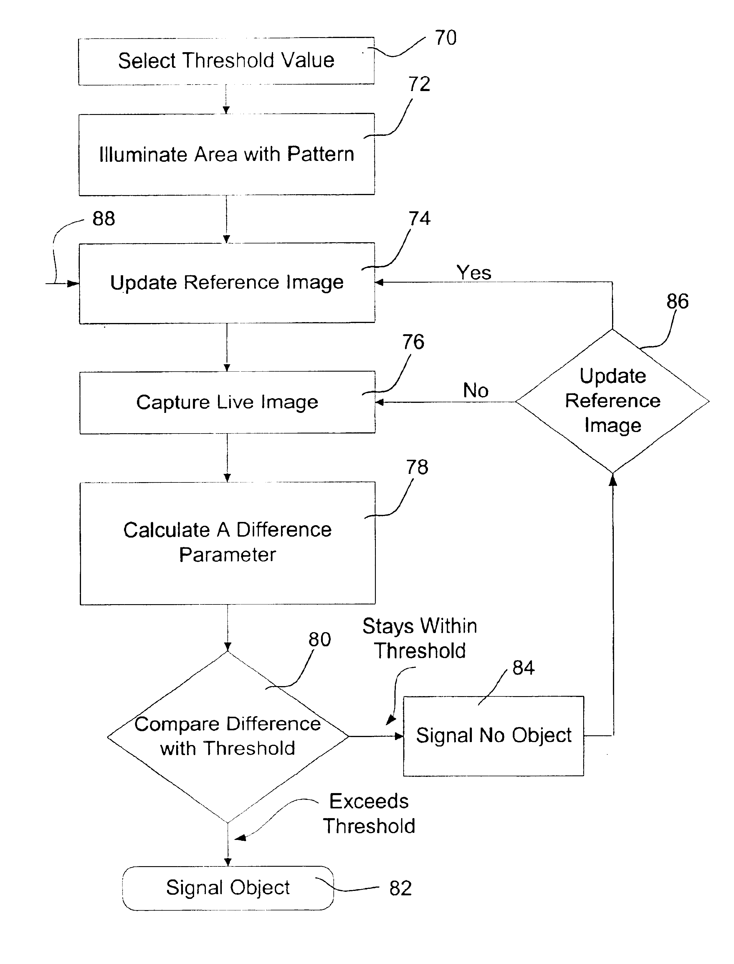
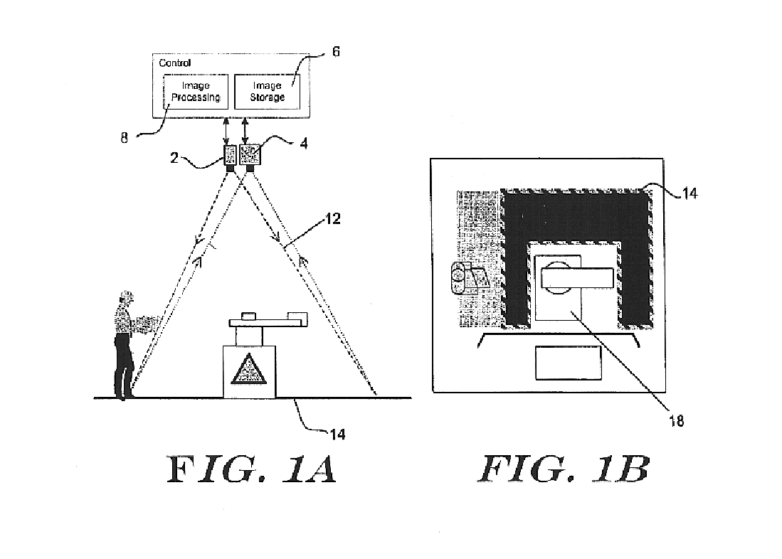
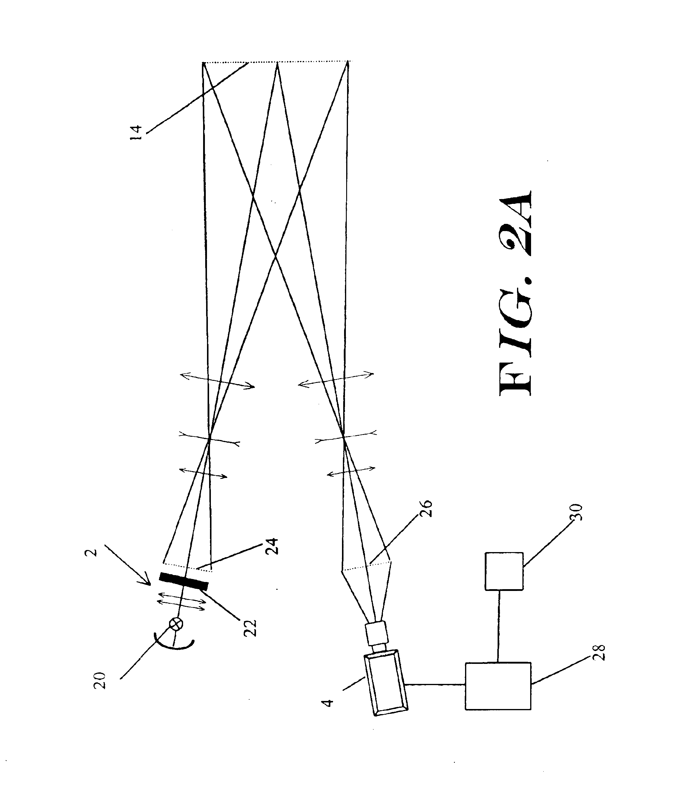
The present invention provides an object detection system that may be less susceptible to dynamic lighting conditions, and / or may be more sensitive to object motion and / or presence than prior art systems. The system is also sensitive to all three-dimensional extraneous objects that intrude into the monitored area. This may be accomplished by, for example, projecting one or more static or dynamic patterns on the monitored area, capturing one or more images of the monitored area including the one or more patterns, and detecting objects in the monitored area by detecting changes in the one or more patterns in selected captured images.

FIGS. 1A-1B are schematic diagrams showing a first illustrative object detection s...


PUM


Abstract

An object detection system is provided that projects one or more patterns onto a monitored area, captures one or more live images of the monitored area, and detects objects that enter the monitored area by detecting changes in the one or more patterns in the live images. Such an object detection system may be less susceptible to dynamic lighting conditions, and more sensitive to object motion and / or presence.

Description

FIELD OF THE INVENTIONThe present invention relates to object detection, and more specifically, to object intrusion and / or presence detection within a monitored area or region.BACKGROUND OF THE INVENTIONMotion detection and object detection systems are well known in the art. Frequently, such systems monitor a user-defined area to detect when an object enters or passes through a monitored area. Such systems typically include an image capture device (typically a video camera or still camera) capable of capturing an image of the monitored area and, if required, a device for digitizing the captured images. The digitized images are analyzed in an attempt to detect whether an object has entered the monitored area. There are many different known methods and algorithms for analyzing digitized images for determining when an object has entered a monitored area. One of the most common methods is generally referred to as a change detection method.Change detection is often accomplished by examin...

Claims


Application Information

Patent Timeline
Patent Type & Authority Patents(United States)
IPC IPC(8): G01B11/25G01B11/24G06T7/20G08B13/194G06T1/00G06T7/00G06V10/145
CPCG01B11/25G06K9/00771G06K9/2036G08B13/19686G06T7/2053G08B13/19602G08B13/19604G06T7/20G06T7/254G06V20/52G06V10/145
Inventor COFER, DARREN D.HAMZA, RIDA M.GIERCZAK, MAREK
Owner HONEYWELL INT INC
Learn More