Multi-activation detection method and device used for intelligent elastic framework

An intelligent elastic architecture and multi-activation detection technology, applied in the field of communication, can solve problems such as business paralysis

Inactive Publication Date: 2011-10-05
NEW H3C TECH CO LTD
View PDF3 Cites 15 Cited by
  • Summary
  • Abstract
  • Description
  • Claims
  • Application Information

AI Technical Summary

Problems solved by technology

Even if the uplink of device 1 is normal, but most of the services of other stack devices are available, most of the services of other stack devices will be paralyzed

Method used


Image

  • Multi-activation detection method and device used for intelligent elastic framework
  • Multi-activation detection method and device used for intelligent elastic framework
  • Multi-activation detection method and device used for intelligent elastic framework

Examples


example 1

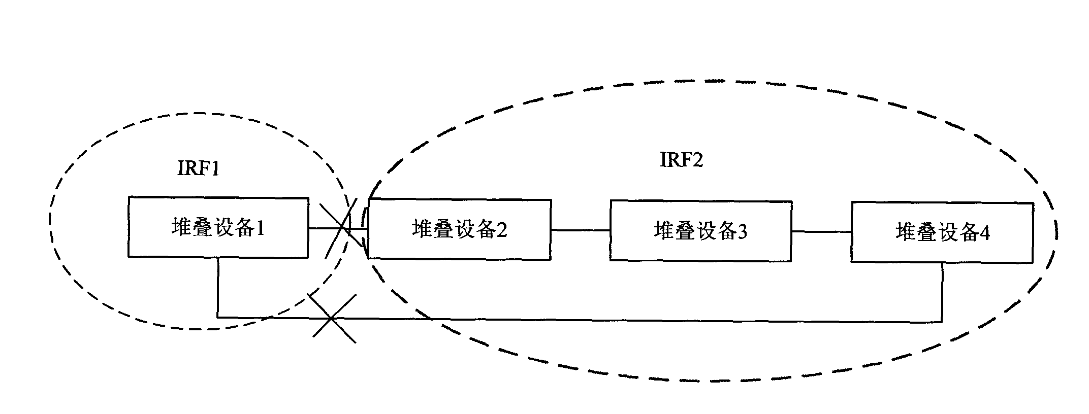
[0052] see Figure 4 , Figure 4 Schematic diagram of the IRF split structure in Example 1.

[0053] exist Figure 4 Among them, four stacking devices constitute an IRF, where the device numbers of stacking device 1, stacking device 2, stacking device 3, and stacking device 4 are member ID 1, member ID2, member ID 3, and member ID 4, assuming that the current IRF The master device is stack device 1, and LACP MAD detection is enabled, and the IRF is interconnected with the uplink device through cross-chassis aggregation.

[0054] Such as Figure 4 In the IRF, when the stacking optical cable between stacking device 2 and stacking device 3 is interrupted, and the stacking optical cable between stacking device 1 and stacking device 4 is interrupted, the original IRF is split into two new stacking group IRFs, where The two member devices of stacking device 1 and stacking device 2 constitute a new stacking group IRF1, and the two member devices of stacking device 3 and stacking ...

example 2

[0058] see Figure 5 , Figure 5 Schematic diagram of the IRF split structure in Example 2.

[0059] exist Figure 5 Among them, four stacking devices constitute an IRF, where the member IDs of stacking device 1, stacking device 2, stacking device 3, and stacking device 4 are member ID 1, member ID2, memberID 3, and member ID 4 respectively. Assume that the current IRF The master device is stack device 1 with LACPMAD detection enabled, and the IRF is interconnected with the uplink device through cross-chassis aggregation.

[0060] Figure 5 , when the stacking optical cable between IRF stacking device 1 and stacking device 2 is interrupted, and the stacking optical cable between stacking device 1 and stacking device 4 is interrupted, the IRF is split into two new stacking groups IRF 1 and IRF2. The master device of IRF 1 (for example, stack device 1) sends an LACP1 packet, which carries the uplink bandwidth of the IRF 1 to which the device belongs, the number of member dev...

example 3

[0063] see Image 6 , Image 6 Schematic diagram of the IRF split structure in Example 3. exist Image 6 Among them, six stacking devices form an IRF, and the member IDs of stacking device 1, stacking device 2, stacking device 3, stacking device 4, stacking device 5, and stacking device 6 are member ID 1, member ID2, memberID 3, member ID 4, member ID 5, and member ID 6, assuming that the current master device of the IRF is stack device 1, LACP MAD detection is enabled, and the IRF is interconnected with the upstream device through cross-chassis aggregation.

[0064] Image 6 In the IRF, when the stacking optical cable between stacking device 2 and stacking device 3 is interrupted, the stacking optical cable between stacking device 4 and stacking device 5 is interrupted, and the stacking optical cable between stacking device 1 and stacking device 6 is interrupted in the IRF, the IRF It is split into three new stack groups, namely IRF1, IRF2, and IRF3, and their uplink band...


PUM


Abstract

The invention discloses a multi-activation detection (MAD) method for an intelligent elastic framework (IRF), which comprises the steps of: receiving MAD messages at least containing an up-link bandwidth and being sent by other main devices by a main device; closing a service port of the device and service ports of the other devices of the IRF belonging to the device when any up-link bandwidth accepted by the main device is larger than the up-link bandwidth of the IRF belonging to the device; and maintaining the normal operation of the IRF belonging to the device when the up-link bandwidth accepted by the main device is smaller than the up-link bandwidth of the IRF belonging to the device. On the basis of the same invention concepts of the method, the invention also provides a device capable avoiding the breakdown status of all the services or most services of a stackable system.

Description

technical field [0001] The present invention relates to the field of communication technology, in particular to a multi-activation detection method and device for an intelligent elastic architecture. Background technique [0002] Intelligent Resilient Framework (IRF) is to connect multiple devices together through IRF ports to form a joint device; and users can manage all devices in the IRF by managing this joint device . It can be seen that by increasing the number of devices in the system, IRF can easily increase the number of ports, bandwidth, and packet processing capabilities of the system, that is, IRF can provide more stable multi-link backup through aggregation between multiple devices. Realize the high reliability of the link. [0003] When the stacking link of the IRF is disconnected, the original IRF will split into two or more IRFs with the same global configuration, and when the split IRFs with the same global configuration run in the network at the same time,...

Claims


Application Information

Patent Timeline
Patent Type & Authority Applications(China)
IPC IPC(8): H04L12/26
Inventor 郭振华
Owner NEW H3C TECH CO LTD
Why Eureka
Try Eureka