Traveling aid device

A technology of driving support and control devices, which is applied in the directions of automatic starting devices, braking action starting devices, transportation and packaging, etc., which can solve the problems of driver discomfort and inability to avoid obstacles, and achieve the effect of reducing discomfort

Active Publication Date: 2011-10-05
HITACHI ASTEMO LTD
View PDF6 Cites 20 Cited by
  • Summary
  • Abstract
  • Description
  • Claims
  • Application Information

AI Technical Summary

Problems solved by technology

Therefore, when only the brakes are used for control, lane departure avoidance can be achieved without discomfort, but since braking control can only generate a smaller yaw moment than steering control, there is a problem that reliable avo

Method used


Image

  • Traveling aid device
  • Traveling aid device
  • Traveling aid device

Examples


Embodiment 1

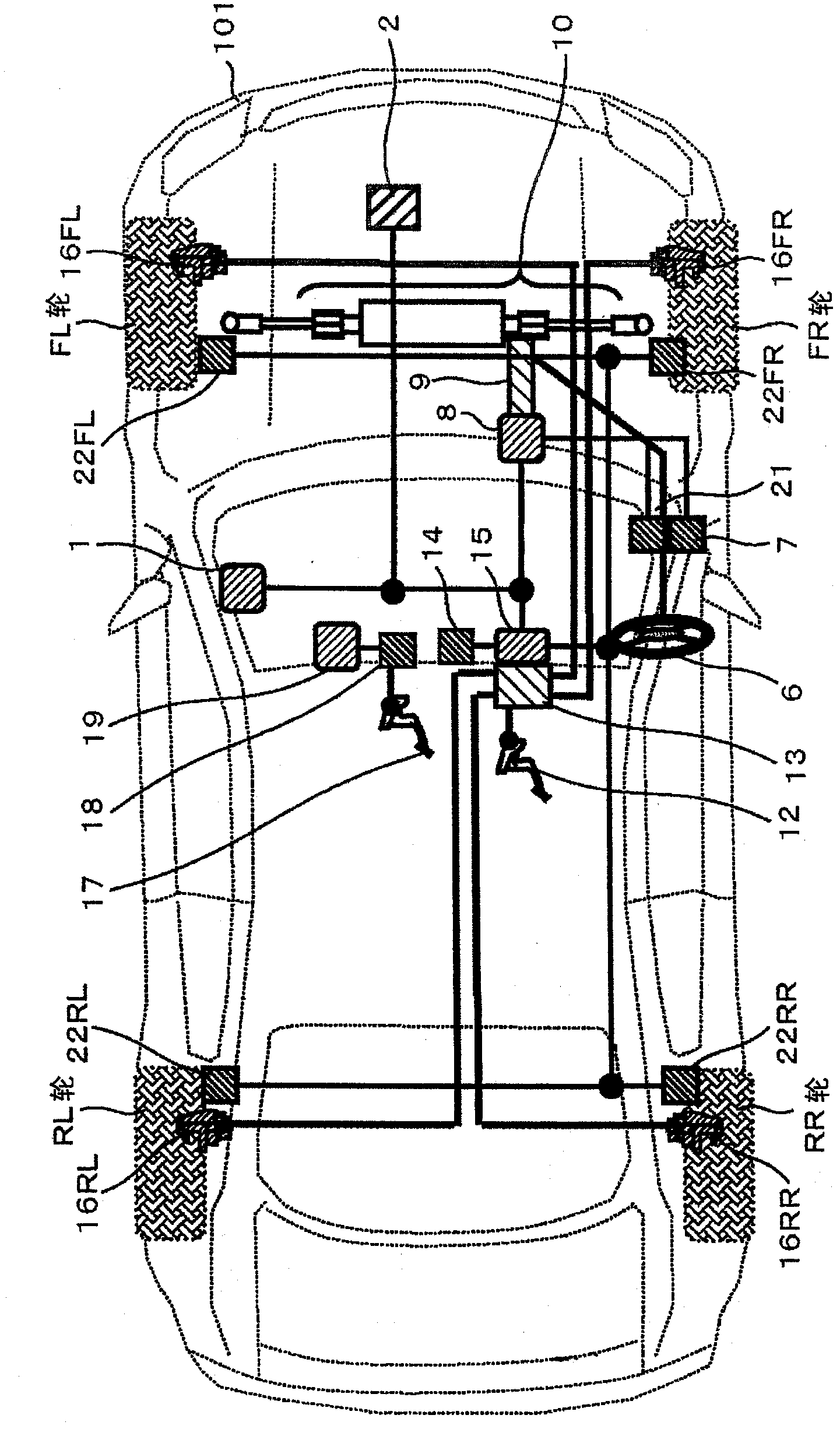
[0034] figure 1 It is a figure which shows a driving assistance device. It should be noted that the FL wheel represents the left front wheel, the FR wheel represents the right front wheel, the RL wheel represents the left rear wheel, and the RR wheel represents the right rear wheel. The driving assistance device 101 includes: a sensor 2 for recognizing the front of the vehicle; various actuators (steering control mechanism 10, brake control mechanism 13) for performing driving assistance based on information obtained by the sensor; The comprehensive control device 1 that calculates the command value of the actuator; the steering control device 8 that controls the steering control mechanism 10 according to the command value from the comprehensive control device 1; Brake control device 15 that adjusts the distribution of braking force to each wheel. The integrated control device 1 , the steering control device 10 , and the brake control device 15 are connected via an in-vehicl...

Embodiment 2

[0062] Hereinafter, Embodiment 2 will be described using the drawings. Figure 9 The system structure is shown in . The second embodiment is an embodiment in which the brake control mechanism 13 and the brake control device 15 of the first embodiment are replaced with the yaw moment control mechanism 24 and the yaw moment control device 25 . Only the parts different from those in Example 1 will be described, and the description of the same parts will be omitted.

[0063] The integrated control device 1 , the steering control device 10 , and the yaw moment control device 2 are connected via an in-vehicle network such as CAN.

[0064] The yaw moment control mechanism 24 will be described. The yaw moment control mechanism 24 connects planetary gears (not shown) arranged in multiple rows between the left and right wheels, and inputs motor torque to a planetary gear on one side, so that the left and right wheels can be driven by a single motor (not shown). produce reverse torque...

Embodiment 3

[0069] Hereinafter, Embodiment 3 will be described using the drawings. to carry figure 1 The illustrated driving assist device 101 of the brake control device 15 is used as an example to illustrate the system structure of the third embodiment, but it may also be a driving assist device equipped with a driving force control device (not shown) and a yaw moment control device 25 . Only the parts different from those in Example 1 will be described, and the description of the same parts will be omitted.

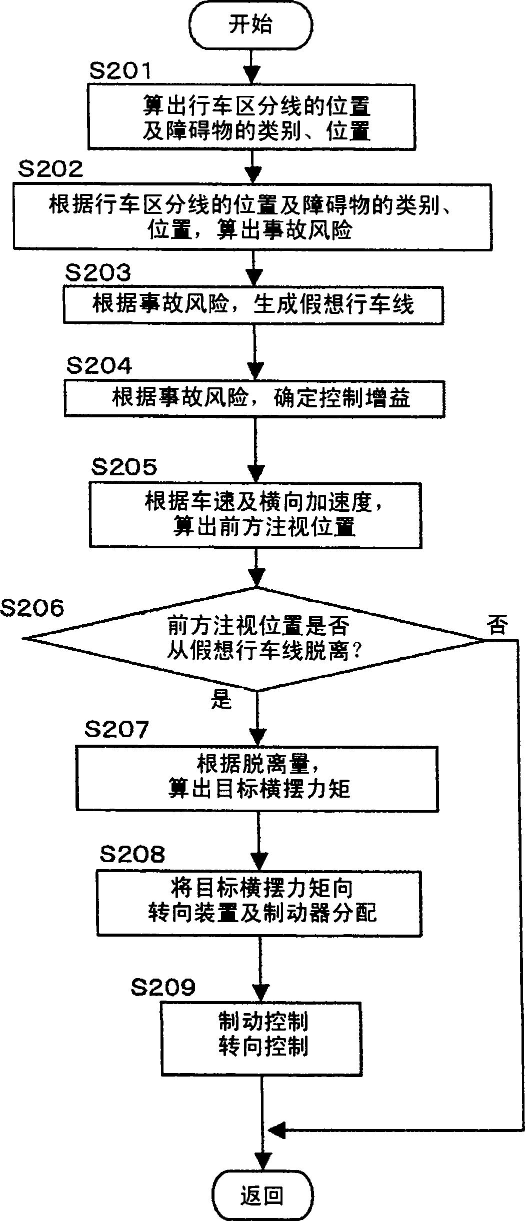
[0070] Except in the flowchart in embodiment 3 figure 2Steps other than S208 are the same as in Embodiment 1. And, the distribution of the target yaw moment is calculated by equations (2) and (3).

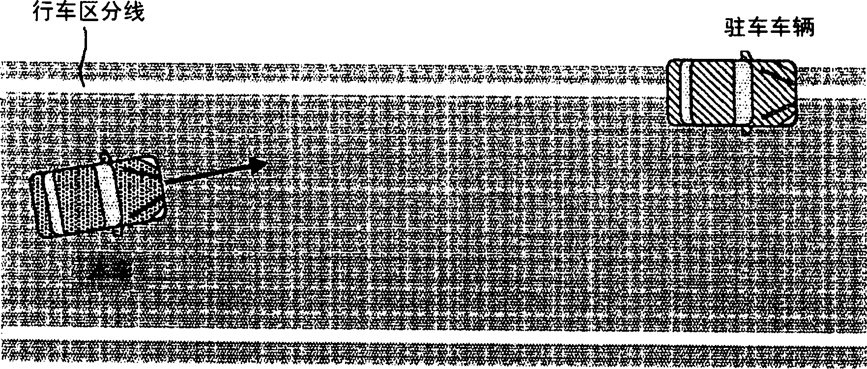
[0071] Next, the distribution method of the target yaw moment will be described. When driving at a high speed (for example, 120km / h) to avoid a collision through steering control, the vehicle's behavior changes greatly, so it is very scary for the driver. On the other hand, a yaw...


PUM


Abstract

A conventional brake control can generate only a small yaw moment compared with a steering control, so that reliable avoidance of obstacles cannot be obtained. With a steering control, the driver gets behind the wheel every time when crossing a lane and has an uncomfortable feeling. To solve these problems, a traveling aid device comprises: a detection unit for detecting the traveling state of a vehicle, the position of a lane marker, and the positions and types of obstacles around the vehicle; a calculation unit for calculating, based on the traveling state of the vehicle, the position of the lane marker, and the positions and types of the surrounding obstacles, a target yaw moment so as to prevent a departure from the lane marker and a collision with the surrounding obstacles; and a distribution unit for distributing, based on at least one of the traveling state of the vehicle, the position of the lane marker, and the positions and types of the surrounding obstacles, the target moment to a first actuator for controlling the driving/braking force and a second actuator for controlling the steering.

Description

technical field [0001] The present invention relates to a driving assistance device for a vehicle. Background technique [0002] As a prior art, there is a technique for preventing the own vehicle from leaving the traffic lane by controlling the braking force applied to the wheels to apply a yaw moment to the own vehicle when the own vehicle is likely to leave the traffic lane. The application of this yaw moment notifies the driver that the own vehicle may depart from the traffic lane (see Patent Document 1). In Patent Document 1, by changing the control amount of lane departure avoidance control (threshold value for departure avoidance control) according to obstacles on the road shoulder, lane departure avoidance control can be performed in consideration of obstacles ahead such as parked vehicles. [0003] Patent Document 1: Japanese Patent Laid-Open No. 2005-324782 [0004] Patent Document 1 describes control using the brakes or the steering, but there is no description ...

Claims


Application Information

Patent Timeline
IPC IPC(8): B60W30/08B60T7/12B60T8/17B60T8/1755B60W10/18B60W10/20B60W30/00B60W30/12B60W40/06G08G1/16B60W10/188B60W30/09B60W40/068
CPCB60T7/042B60T2201/087B60T7/22B60W30/12B60T8/17558B62D15/025B62D6/003B60W2720/14B60T8/17557B62D15/0265B60T2201/083
Inventor 菅原俊晴横山笃
Owner HITACHI ASTEMO LTD
Why Eureka
Try Eureka