Connector device

一种连接器、一对的技术,应用在两部件连接装置、连接装置的零部件、连接等方向,能够解决操作杆无法发挥作用、操作杆晃动、异常噪音等问题

Active Publication Date: 2011-10-05
I PEX CO LTD
View PDF1 Cites 6 Cited by
  • Summary
  • Abstract
  • Description
  • Claims
  • Application Information

AI Technical Summary

Problems solved by technology

Therefore, when an external force that displaces both or one of the pair of end portions in a direction toward the outside of the insulating housing of the first connector acts on the lever provided on the insulating housing of the first connector, the It is possible for the end to undesirably come out of the first connector, rendering the lever useless
[0010] In addition, in the above-mentioned conventional connector device, a pair of rotating shaft parts constituted by a pair of end parts of the operating rod provided on the insulating case of the first connector are inserted and installed in a loosely fitted state in a freely rotatable manner, respectively. At both ends in the longitudinal direction of the insulating housing of the first connector, the main operating portion of the operating lever is close to a portion of the insulating housing of the second connector on the opposite side of the fitting recess, And when going over this part and engaging with the locking and locking part provided on the conductive housing of the second connector, the pair of rotating shaft parts formed by the pair of ends are respectively in a loose fit state with the pair of rotating shaft parts. A gap is formed between the insulating housings of the inserted first connector, and thus, a gap is formed between the main operating part of the operating lever and the second connector, causing "wobbling" of the operating lever and abnormal noise. bad situation

Method used


Image

  • Connector device
  • Connector device
  • Connector device

Examples


Embodiment 1

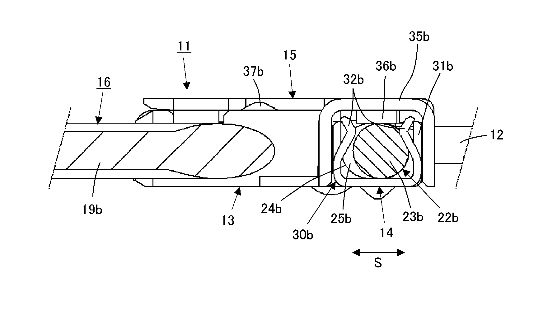
[0051] figure 1 and figure 2 An example (Example 1) of the connector device of the present invention is shown together with a plurality of cables connected thereto.

[0052] exist figure 1 and figure 2 In the embodiment 1, the connector device 11 constituting the first embodiment is used as a side connector device such as a cable, for example, on the basis of electrically connecting a plurality of coaxial cables 12, and is embedded, for example, with a counterpart connector device as a substrate side connector device. Accordingly, the substrate-side connector device is mounted on the substrate as a rigid printed circuit board so as to be electrically connected to the circuit configuration portion provided on the substrate. Furthermore, the connector device 11 is provided with: an insulating case 13, which is formed by an insulating material such as synthetic resin; a conductive shell 14 and a conductive cover 15, which partially cover the outer surface of the insulating...

Embodiment 2

[0098] Figure 13 The operation lever 56 included in another example (Example 2) of the connector device of the present invention is shown as a single body.

[0099] have Figure 13 The portion other than the operation lever 56 in the second embodiment of the illustrated operation lever 56 has the same configuration as that of the above-mentioned embodiment 1 (connector device 11 ). Therefore, for the parts of the second embodiment having the same configuration as the first embodiment, overall detailed description is omitted, and the parts corresponding to the first embodiment are given the same reference numerals, and the parts requiring explanation are shown and described. And, in Embodiment 2, the same plurality of coaxial cables 12 as the plurality of coaxial cables 12 electrically connected in Embodiment 1 are electrically connected in the same manner as the manner in which the plurality of coaxial cables 12 are electrically connected in Embodiment 1. , In addition, in ...

Embodiment 3

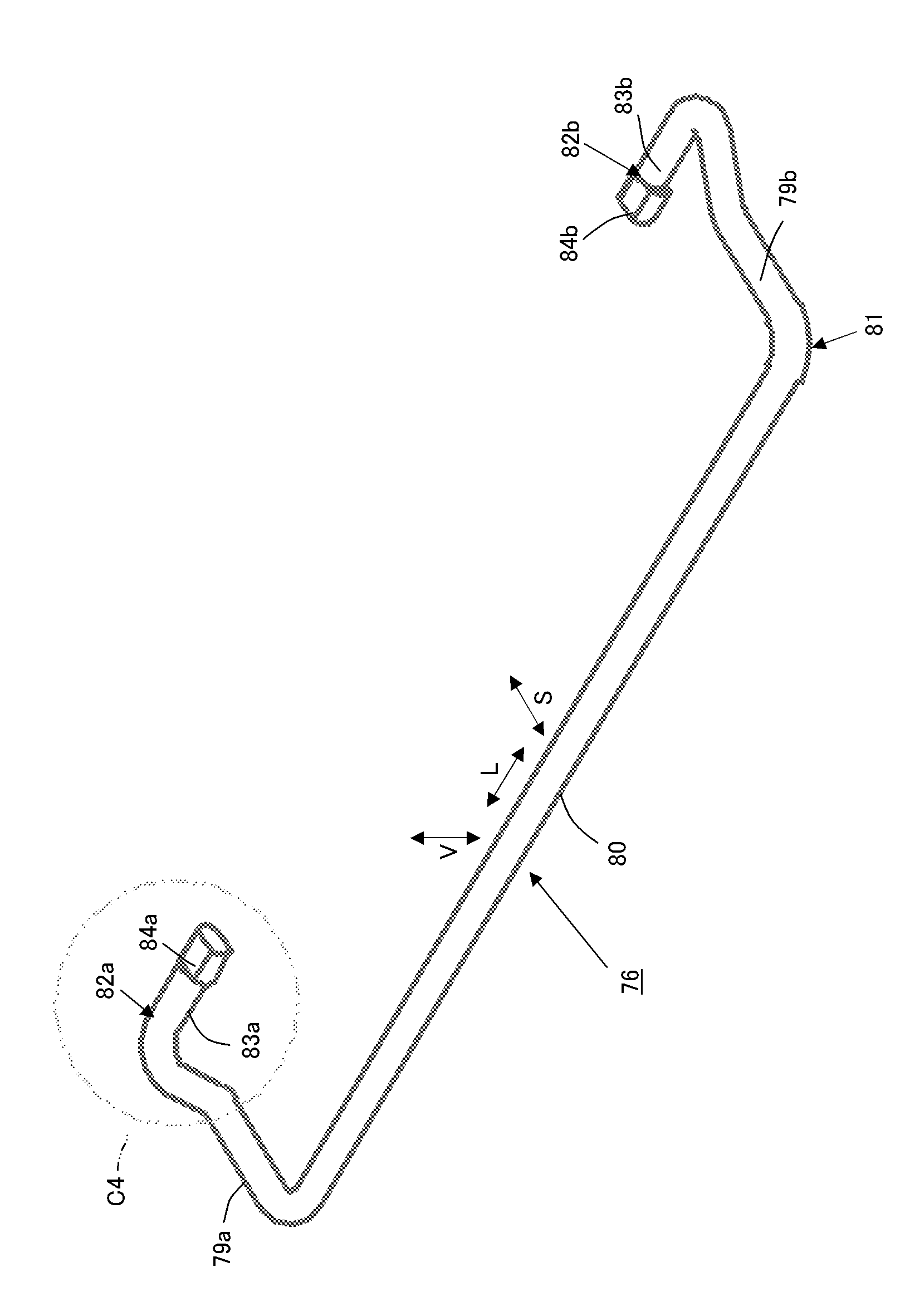
[0132] Figure 18 The operation lever 76 included in yet another example (Example 3) of the connector device of the present invention is shown as a single body.

[0133] have Figure 18Also in Example 3 of the illustrated operating lever 76 , parts other than the operating lever 76 are configured in the same manner as in the aforementioned Example 1 (connector device 11 ). Therefore, for the parts of the third embodiment having the same configuration as the first embodiment, overall detailed description will be omitted, and the parts corresponding to the first embodiment will be denoted by the same reference numerals, and the parts requiring explanation will be shown and described. In addition, in the third embodiment, the same plurality of coaxial cables 12 as the plurality of coaxial cables 12 in the first embodiment are electrically connected in the same manner as the plurality of coaxial cables 12 in the first embodiment. , In addition, in Embodiment 3, it is fitted to t...


PUM


Abstract

A connector device that includes an operation lever having both ends supported by a conductive shell covering an insulating housing partially for engagement with a mating connector device, wherein undesirable detachment of both ends on the operation lever from the conductive shell is prevented without fail. Both ends (22a, 22b) on an operation lever (16) have extended parts (23a / 23b) crookedly continuing to a main body part (21) and further continuing front edge parts (24a / 24b) respectively, extending in a first direction from the end to the center of an insulating housing (13). When the front edge parts are displaced in parallel in the direction orthogonal to the central axis direction of the extended parts to form step parts (25a / 25b) at the border between the extended parts, and are made to be displaced toward a second direction opposite to the first direction under a condition of being supported by support mechanisms (30a / 30b), latching parts (32a / 32b) provided on the support mechanisms at the step parts are engaged to prevent detachment from the support mechanisms.

Description

technical field [0001] The present invention relates to a connector device. On the basis of connecting a cable or a flexible printed circuit board (FPC), for example, it is in a state of being fitted with a counterpart connector device mounted on a main substrate such as a rigid printed circuit board, and realizes a cable or a flexible printed circuit board (FPC). Electrical connection between FPC, etc., and the counterpart connector device. Background technique [0002] When a plurality of thinner cables or smaller FPCs are electrically connected to a main substrate such as a rigid printed circuit board on which various electrical components are mounted, the first connector device and the second connector device are often used. The connector device is a side connector device such as a cable connected to a plurality of cables or FPC, and the second connector device is used as a substrate-side connector device, mounted on the main substrate and electrically connected to the m...

Claims


Application Information

Patent Timeline
Patent Type & Authority Applications(China)
IPC IPC(8): H01R13/639
CPCH01R13/62933H01R13/6335H01R23/684H01R12/88H01R12/71H01R13/639H01R13/648
Inventor 田川哲也碇泰治
Owner I PEX CO LTD
Why Eureka
Try Eureka