Eureka AIR delivers breakthrough ideas for toughest innovation challenges, trusted by R&D personnel around the world.

Automated analysis device with an automatic pipetting device and a pipetting needle rinsing station

A suction needle, automatic technology, applied in the direction of analysis materials, laboratory equipment, chemical instruments and methods, etc.

Inactive Publication Date: 2011-10-12
DIASYS TECH R L
View PDF4 Cites 1 Cited by
  • Summary
  • Abstract
  • Description
  • Claims
  • Application Information

AI Technical Summary

Problems solved by technology

Immersing the needle in irrigation fluid, in which the irrigation fluid is drawn into the needle, and then expelled through the needle, even in combination with a wiping action that wipes the liquid from the outside of the needle, is not always as effective effective as required

Method used


Image

  • Automated analysis device with an automatic pipetting device and a pipetting needle rinsing station
  • Automated analysis device with an automatic pipetting device and a pipetting needle rinsing station
  • Automated analysis device with an automatic pipetting device and a pipetting needle rinsing station

Examples


Embodiment Construction

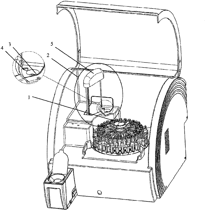
[0060] figure 1 A device for the automatic analysis of liquids (analyzer) is shown, which has a carousel 1 for liquid containers and a pipetting device 2 with a pipetting arm 5 . The carousel 1 is arranged to move liquid containers into the working area of ​​the pipetting arm 5 . Furthermore, a rinsing station 3 and a measuring device 4 for determining the exact position of the tip of the pipetting needle are also arranged in the working area of ​​the pipetting arm 5 .

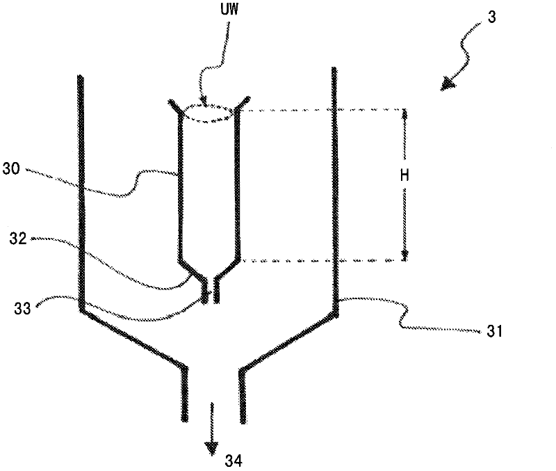
[0061] figure 2 The rinsing station 3 of the present invention is schematically shown in . A hollow cylindrical washing basin with an opening at the top is arranged in a drip tray 31 , and a discharge pipe 34 is arranged in the drip tray 31 , wherein the height of the hollow cylinder is defined as H. The hollow cylinder has an inner circumference UW. At the upper edge of the hollow cylinder, the wash basin 30 is made slightly wider towards the outside. In this embodiment, the bottom of the wash basin 32 ...


PUM


Abstract

The invention relates to an automatic pipetting device comprising a rinsing station for rinsing the pipetting needle, wherein the rinsing station comprises at least one rinsing bowl which is opened upward, said bowl having a height corresponding to at least a predefined maximum submersion depth of the pipetting needle into a working liquid during an automated pipetting process. The inner circumference of the rinse bowl is larger than the outer circumference of the pipetting needle and a rinsing bowl base and a rinsing bowl drain are located at the lower end of the rinsing bowl. In order to provide a rinse station for rinsing a pipetting needle, said station quickly and efficiently providing an as optimum as possible inner and outer cleaning of a pipetting needle as possible between pipetting processes with little effort and using low amounts of rinsing liquid, according to the invention a rinse station is proposed wherein the hydraulic drainage friction of the rinse bowl drain is selected such that the flow rate of the rinse liquid is greater than the drainage rate (volume per time) of the rinse liquid through the rinse bowl drain at a given flow rate (volume per time) of a specific rinse liquid through the pipetting needle to the rinse bowl.

Description

technical field [0001] The invention relates to an automatic liquid suction device having a flushing station for flushing a suction needle of the liquid suction device, wherein the flushing station comprises at least one flush basin open at the top, the height of which is Corresponding to at least a specified maximum immersion depth (T) of the pipetting needle in the sample or reagent liquid during the automatic pipetting operation, the inner circumference of the washing basin is larger than the outer circumference of the pipetting needle and has a flushing A bowl base and a wash basin drain disposed within or directly above the wash basin base. Furthermore, the invention relates to an automatic analysis device with the automatic pipetting device and a method for flushing a pipetting needle of the automatic pipetting device. Background technique [0002] In the field of increasing automation in the range of human or veterinary medical diagnosis, devices for automatically an...

Claims


Application Information

Patent Timeline
IPC IPC(8): G01N35/10
CPCB01L3/021B01L13/02B01L2200/143G01N35/1004
Inventor R·塞恩基
Owner DIASYS TECH R L
Why Eureka
Eureka Blog
Learn More