Light mixing device

A light mixing device and light mixing technology, applied in the optical field, can solve the problems of increasing design difficulty and production cost, uneven light mixing, increasing the arrangement of light sources, etc., and achieve the effects of being conducive to heat dissipation, simple design, and improved energy flow density

Inactive Publication Date: 2011-10-19
ZHEJIANG JINGRI LIGHTING TECH
View PDF5 Cites 2 Cited by
  • Summary
  • Abstract
  • Description
  • Claims
  • Application Information

AI Technical Summary

Problems solved by technology

[0003] In order to achieve a better color mixing effect, the existing light mixing devices have very high requirements on the arrangement accuracy of the light sources and the design and processing of the lenses used, and all the light mixing light sources are located on the same plane (substrate) in a certain arrangement. Increase the arrangement of light sources, that is, increase the difficulty of heat dissipation of light sources
In addition, this kind of device also puts forward higher precision requirements for the assembly of lamps, and it is easy to have uneven light mixing, which greatly reduces the yield of mixed light LED lamps, and also increases design difficulty and production costs.

Method used


Image

  • Light mixing device
  • Light mixing device
  • Light mixing device

Examples


Embodiment 1

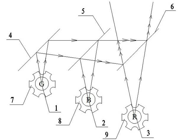
[0025] Embodiment 1: as figure 1 As shown, a light mixing device includes a first primary color light source 1 , a second primary color light source 2 , a third primary color light source 3 , a first projection device 4 , a second projection device 5 , and a third projection device 6 . The first projection device 4, the second projection device 5, and the third projection device 6 are coated glass plates and are arranged in parallel, and the angle between them and the horizontal direction is 45°. o . The first primary color light source 1 , the second primary color light source 2 , and the third primary color light source 3 are green, blue, and red LED light sources respectively, and they are respectively fixed on the first substrate 7 , the second substrate 8 , and the third substrate 9 . The first primary color light source 1, the second primary color light source 2, and the third primary color light source 3 respectively emit the first primary color light, the second prima...

Embodiment 2

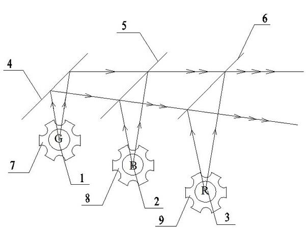
[0026] Embodiment 2: as figure 2 As shown, a light mixing device includes a first primary color light source 1 , a second primary color light source 2 , a third primary color light source 3 , a first projection device 4 , a second projection device 5 , and a third projection device 6 . The first projection device 4, the second projection device 5, and the third projection device 6 are coated glass plates and are arranged in parallel, and the angle between them and the horizontal direction is 45°. o . The first primary color light source 1 , the second primary color light source 2 , and the third primary color light source 3 are green, blue, and red LED light sources respectively, and they are respectively fixed on the first substrate 7 , the second substrate 8 , and the third substrate 9 . The first primary color light source 1, the second primary color light source 2, and the third primary color light source 3 respectively emit the first primary color light, the second prim...

Embodiment 3

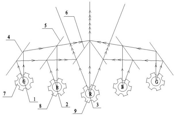
[0027] Embodiment 3: as image 3 As shown, a light mixing device with a predetermined shape of the light outlet, including two light mixing units, the two light mixing units according to the following image 3 In the arrangement shown, each light mixing unit includes a first primary color light source 1, a second primary color light source 2, a third primary color light source 3, and a first projection device 4 that transmits the first primary color light emitted by the first primary color light source 1 ; The second projection device 5 that transmits the first primary color light emitted by the first primary color light source 1 and reflects the second primary color light emitted by the second primary color light source 2; reflects the first primary color light, the second primary color light and transmits the third primary color The third primary color light emitted by the light source 3 . Wherein, the first projection device 4, the second projection device 5, and the third...


PUM


Abstract

The invention relates to a light mixing device comprising a first primary color light source, a second primary color light source, a third primary color light source, a first projecting device, a second projecting device and a third projecting device, wherein the first projecting device is used for transmitting first primary color light emitted by the first primary color light source; the second projecting device is used for transmitting the first primary color light emitted by the first primary color light source and reflecting second primary color light emitted by the second primary color light source; and the third projecting device is used for reflecting the first primary color light and the second primary color light and transmitting third primary color light emitted by the third primary color light source, or is used for transmitting the first primary color light and the second primary color light and reflecting the third primary color light emitted by the third primary color light source. The light mixing device has the advantages that the light mixing is uniform, the design is simple, the radiating is excellent, and the like.

Description

technical field [0001] The invention belongs to the field of optical technology, and in particular relates to a light mixing device. Background technique [0002] The effect of the existing light sources is not very satisfactory when used alone. In order to give full play to the characteristics of various light sources, a light mixing device is needed. LED light sources are widely used in light mixing devices due to their advantages of high stability, fast response, small size, narrow spectral lines, high luminous color purity, and high brightness. The existing LED light mixing device includes a substrate, which is welded on the substrate according to certain geometric rules and has a certain amount of red, green and blue LED light sources with a certain ratio. The light rays are reflected by the lens to form mixed light. [0003] In order to achieve a better color mixing effect, the existing light mixing devices have very high requirements on the arrangement accuracy of t...

Claims


Application Information

Patent Timeline
Patent Type & Authority Applications(China)
IPC IPC(8): F21S2/00F21V13/00F21V19/00F21Y101/02F21Y115/10
Inventor 付创业程世友张磊
Owner ZHEJIANG JINGRI LIGHTING TECH
Why Eureka
Try Eureka