Backlight module, backlight module manufacturing method and display device

A technology for backlight modules and display devices, applied in optics, nonlinear optics, instruments, etc., can solve the problems of thick backlight film layer and difficulty in obtaining uniform light mixing, and achieve the effect of light and thin structure setting

Active Publication Date: 2021-09-24
WUHAN CHINA STAR OPTOELECTRONICS TECH CO LTD
View PDF6 Cites 2 Cited by
  • Summary
  • Abstract
  • Description
  • Claims
  • Application Information

AI Technical Summary

Problems solved by technology

[0004] The embodiment of the present application provides a backlight module, a manufacturing method of the backlight module, and a display device, which can solve the problem that the thickness of the MiniLED backlight film is thick and it is difficult to obtain a surface light source with uniform mixed light

Method used


Image

  • Backlight module, backlight module manufacturing method and display device
  • Backlight module, backlight module manufacturing method and display device
  • Backlight module, backlight module manufacturing method and display device

Examples


Embodiment 1

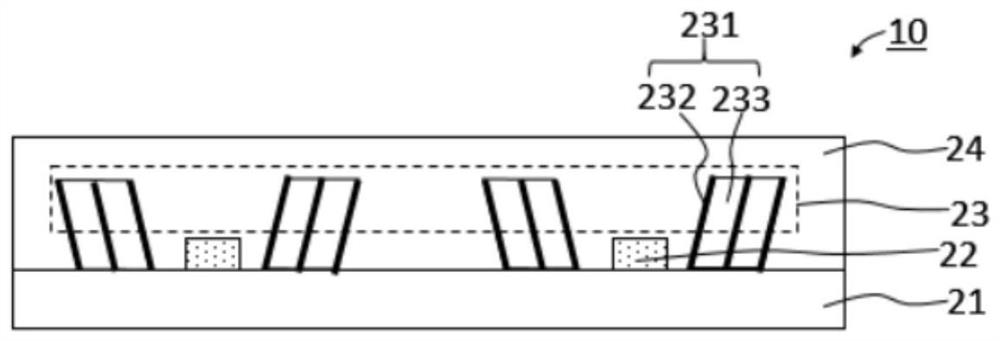
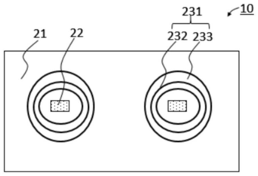
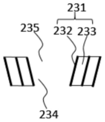
[0040] see figure 1 , figure 2 , image 3 , figure 1 It is a schematic diagram of the first cross-sectional structure of the backlight module provided in the embodiment of the present application, figure 2 It is a schematic diagram of the first top view structure of the backlight module provided by the embodiment of the present application, image 3 A schematic cross-sectional structure diagram of a transflective unit provided in an embodiment of the present application.

[0041] The embodiment of the application provides a backlight module 10 . The backlight module 10 includes a substrate 21 , a light emitting diode 22 , a transflective layer 23 and an encapsulation layer 24 . The light-emitting diode 22 is arranged on the base 21; the transflective layer 23 is arranged on the base, the transflective layer 23 includes a plurality of transflective units 231, and the transflective unit 231 includes at least one transparent carrier film layer 233 and at least one A transf...

Embodiment 2

[0061] see Figure 7 , Figure 7 It is a schematic diagram of the third cross-sectional structure of the backlight module provided by the embodiment of the present application. The structure of the embodiment of the present application is the same or similar to that of the first embodiment. In the direction away from the light emitting diode 22 , the thickness of the transflective film layer 232 of the same transflective unit 231 increases or decreases gradually.

[0062] Specifically, the light emitted by the light emitting diode 22 has the maximum brightness when passing through the nearest first semi-transparent reflective film layer 232, and the brightness decreases when it reaches the second semi-transparent reflective film layer 232, and reaches the third semi-transparent reflective film layer. When the film layer 232, the brightness is further reduced, and the thickness of the semi-transparent reflective film layer 232 of the same semi-transparent reflective unit 231 i...

Embodiment 3

[0066] see Figure 8 , Figure 9 to Figure 15 , the embodiment of the present application also provides a backlight module manufacturing method, Figure 8 A schematic diagram of the process steps of the backlight module manufacturing method provided by the embodiment of the present application is shown, Figure 9 to Figure 15 The manufacturing process of the backlight module is illustrated. The backlight module manufacturing method of this embodiment can be used to manufacture the backlight module 10 of any one of the above-mentioned embodiments. The backlight module manufacturing method includes the following manufacturing steps: step S100, step S200, step S300, step S400, step S500, Step S600.

[0067] Step S100, such as Figure 9 As shown, a mold substrate 30 is provided, including a plurality of recesses 31 in the mold substrate 30 .

[0068] Specifically, such as Figure 9 As shown, a mold substrate 30 is provided, the mold substrate 30 includes a plurality of depre...


PUM


Abstract

The embodiment of the invention discloses a backlight module, a backlight module manufacturing method and a display device. The backlight module comprises a substrate; a light emitting diode arranged on the substrate; a semi-transparent reflection layer arranged on the substrate, wherein the semi-transparent reflection layer comprises a plurality of semi-transparent reflection units, each semi-transparent reflection unit comprises at least one transparent bearing film layer and at least one semi-transparent reflection film layer, and the semi-transparent reflection units are arranged around the light emitting diode; and a packaging layer which covers one side, far away from the substrate, of the semi-transparent reflection layer. The backlight module provided by the embodiment of the invention has a light and thin structure, and can obtain an area light source with uniform light mixing.

Description

technical field [0001] The present application relates to the field of display, in particular to a backlight module, a manufacturing method of the backlight module, and a display device. Background technique [0002] Miniature light-emitting diodes (Mini LED or Micro LED) have been used in display panels. For example, Mini LED is used as the backlight of liquid crystal display panels. Mini LED backlights are currently attracting more and more attention because of their high brightness, high contrast, low power consumption and high reliability. The unique advantages determine that it has significant application advantages in various consumer electronic products such as notebooks and tablets. [0003] However, since the Mini LED backlight is a direct backlight lighting structure, it requires a large light mixing distance or a large number of diaphragms to achieve uniform light mixing in the entire backlight, which is not possible for most consumer electronics products. Accept...

Claims


Application Information

Patent Timeline
Patent Type & Authority Applications(China)
IPC IPC(8): G02F1/13357G02F1/1333
CPCG02F1/133603G02F1/133605G02F1/133611G02F1/1333
Inventor 杨勇
Owner WUHAN CHINA STAR OPTOELECTRONICS TECH CO LTD
Why Eureka
Try Eureka