
A cabinet splicing device with metal armored removable switchgear

A switchgear and metal armoring technology, which is applied in the splicing structure field of metal armored removable switchgear cabinets, can solve problems such as mismatching of basic dimensions, and achieve the effect of simple and convenient operation

Active Publication Date: 2014-10-01
SHANGHAI NAJIE COMPLETE SETAB OF ELECTRIC
View PDF3 Cites 0 Cited by
  • Summary
  • Abstract
  • Description
  • Claims
  • Application Information

AI Technical Summary

Problems solved by technology

[0003] In view of the above problems, the main purpose of the present invention is to provide a method for splicing cabinets with metal armored removable switchgear, which can realize free splicing between cabinets, and solve the problem of current metal armored cabinets in the transformation of current switch cabinets. The problem that the basic size of the removable switchgear cabinet does not match the original cabinet

Method used


Image

  • A cabinet splicing device with metal armored removable switchgear
  • A cabinet splicing device with metal armored removable switchgear
  • A cabinet splicing device with metal armored removable switchgear

Examples


Embodiment Construction

[0011] Combine below Figure 1 to Figure 3 The preferred embodiment of the present invention will be described in detail.

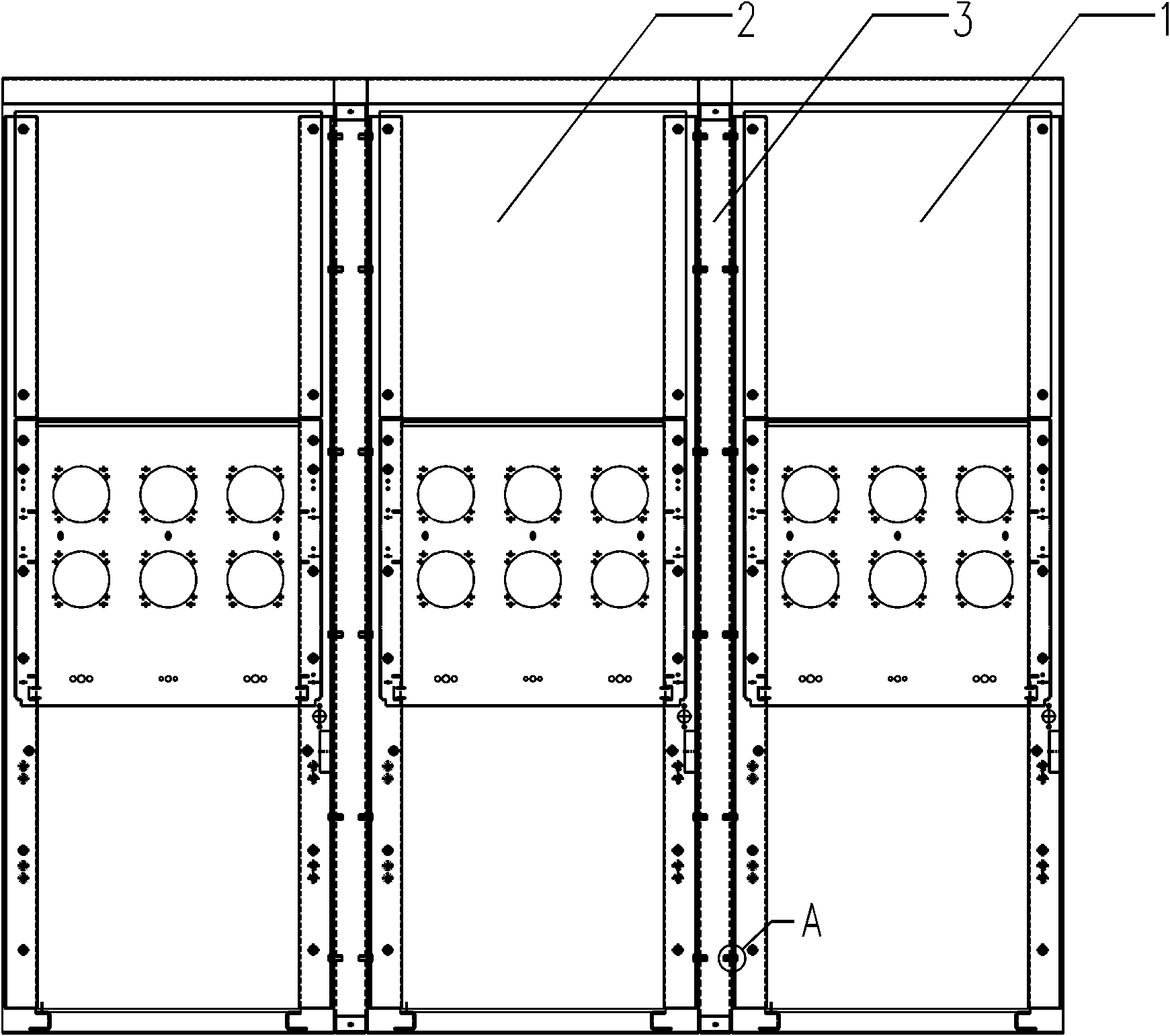
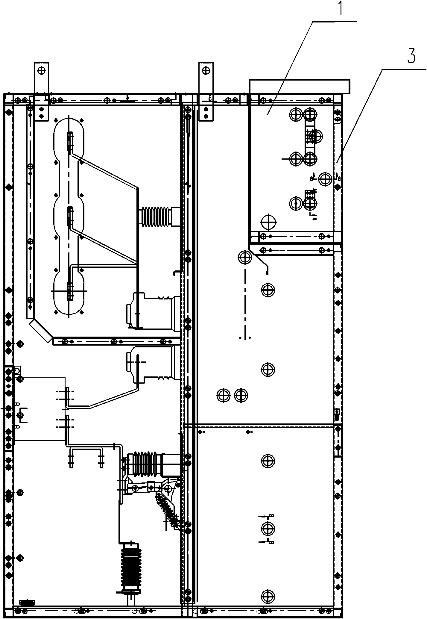
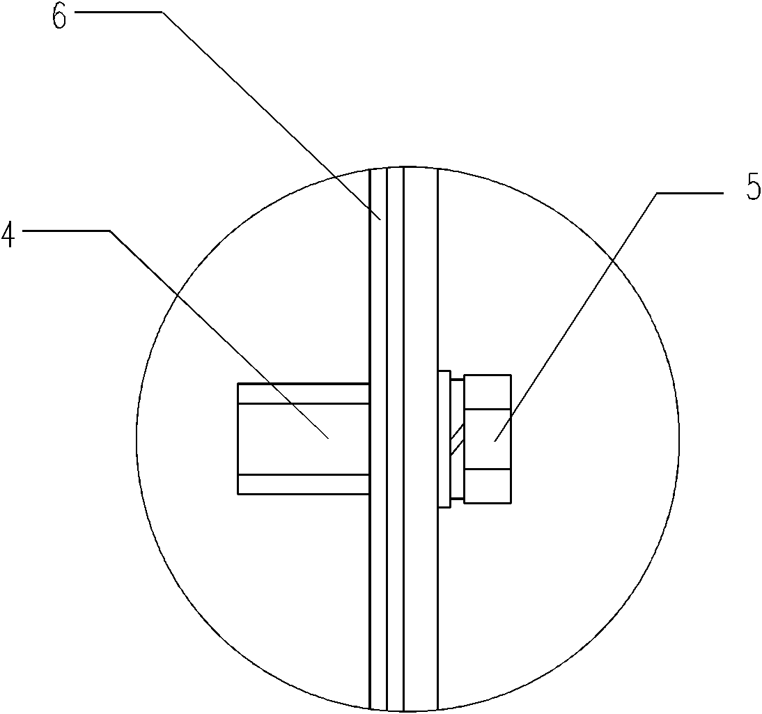
[0012] The present invention relates to a cabinet splicing structure with metal armored removable switchgear, figure 1 is the front view of the present invention, figure 2 It is a cross-sectional view of the present invention at the splicing structure, image 3 is the invention figure 1 Enlarged image at A. As can be seen from the figure, the splicing structure 3 is located between the first cabinet body 1 and the second cabinet body 2, and the first cabinet body 1 and the second cabinet body 2 are spliced ​​together through the splicing structure 3, wherein the splicing structure 3 is A quadrilateral frame whose height and length are equal to those of the first cabinet body 1 and the second cabinet body 2, and the cross-section of the splicing structure 3 is " ”, nuts 4 are installed on the inner sides of the two side panels of the splicing struct...


PUM


Abstract

The invention discloses a splicing structure matched with a metal armoring for a withdrawal-type switch equipment cabinet body, consisting of a first cabinet body (1), a second cabinet body (2) and a splicing structure (3), wherein the first cabinet body (1) and the second cabinet body (2) are spliced together with each other by the splicing structure (3); the first cabinet body (1), the second cabinet body (2) and the splicing structure (3) are connected with one another in sequence by bolts and nuts; the splicing structure (3) adopts a frame type; the width of the cross section of the splicing structure (3) can be determined according to the original fundamental dimension and the current metal armoring withdrawal-type switch equipment switch body, thus very conveniently adjusting the distance between the two cabinet bodies; therefore, the dimension of a reconstructed cabinet body can be well matched with the original fundamental dimension; and the cabinet body and the splicing structure can be well connected with each other by the form of the bolts and the nuts, thus being operated simply and conveniently.

Description

technical field [0001] The invention relates to a metal armored removable switchgear cabinet, in particular to a metal armored removable switchgear cabinet splicing structure, which can realize the convenient adjustment of the distance between the cabinets. Background technique [0002] With the continuous development of 10kV switchgear technology and the influx of foreign advanced technology, the original welded cabinet structure and floor-standing handcart structure have been basically eliminated (original switchgear KYN1, JYN2, XGN, GG1A and other 10kV switchgear obsolete). Nowadays, the above-mentioned cabinets produced more than ten years ago are basically at the limit of their service life; nowadays, there are more and more renovation projects, most of which use the metal armored removable switchgear with quite mature technology to replace the original products. , to reduce costs as much as possible, often use the original equipment infrastructure, use the original ca...

Claims


Application Information

Patent Timeline
Patent Type & Authority Patents(China)
IPC IPC(8): H02B13/02
Inventor 沈春延
Owner SHANGHAI NAJIE COMPLETE SETAB OF ELECTRIC
Learn More