
Finger tip tool maintainer

A technology for tool holders and tool holders, applied in the manufacture of tools, hand-held tools, etc., which can solve the problems of difficult access of tools and tool holders installed on fingers

Inactive Publication Date: 2011-11-09
波莱尔斯解决方案有限公司
View PDF3 Cites 3 Cited by
  • Summary
  • Abstract
  • Description
  • Claims
  • Application Information

AI Technical Summary

Problems solved by technology

[0002] Finger-mounted tools and tool holders are well known in the art for use in hard-to-reach areas

Method used


Image

  • Finger tip tool maintainer
  • Finger tip tool maintainer
  • Finger tip tool maintainer

Examples


Embodiment Construction

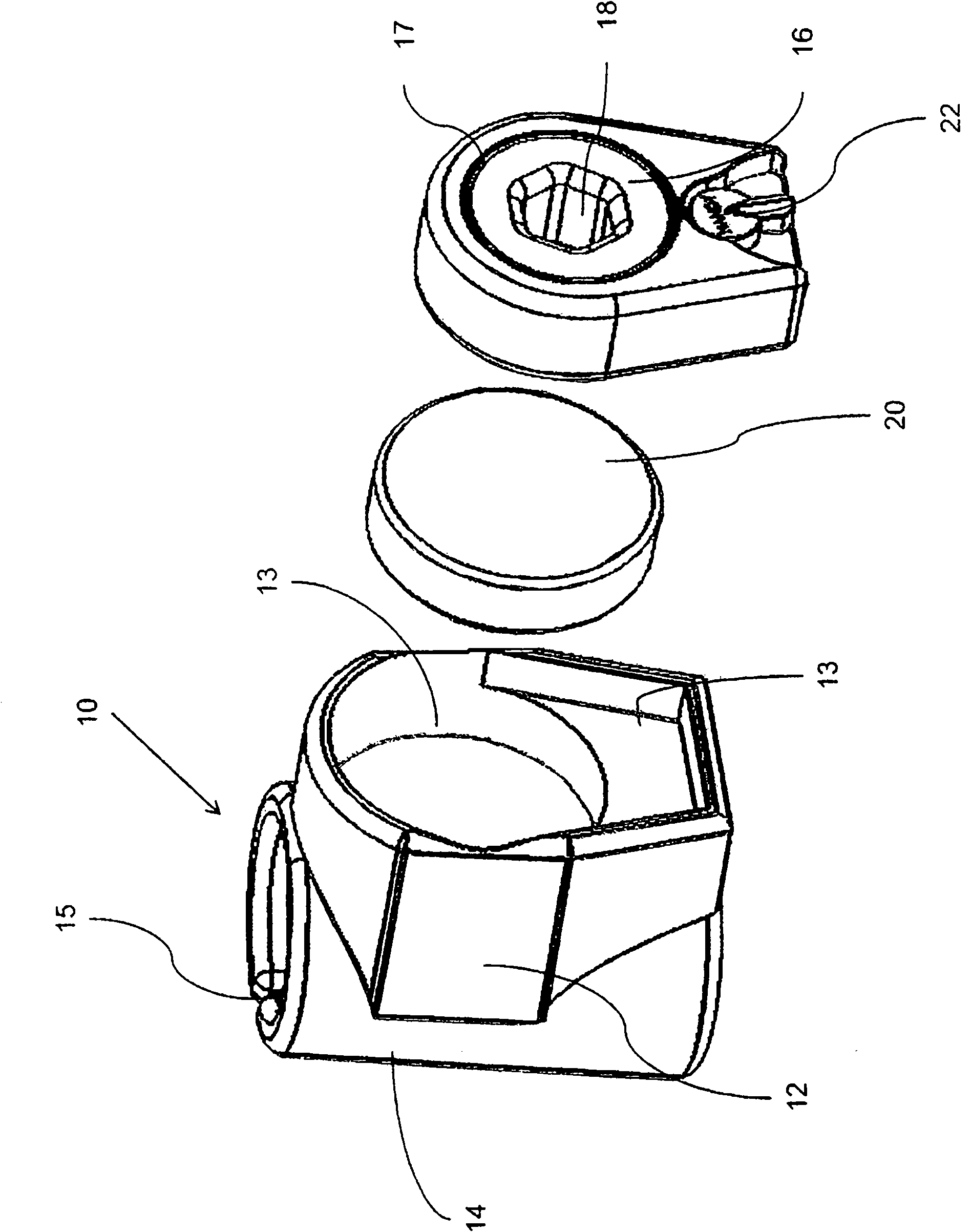
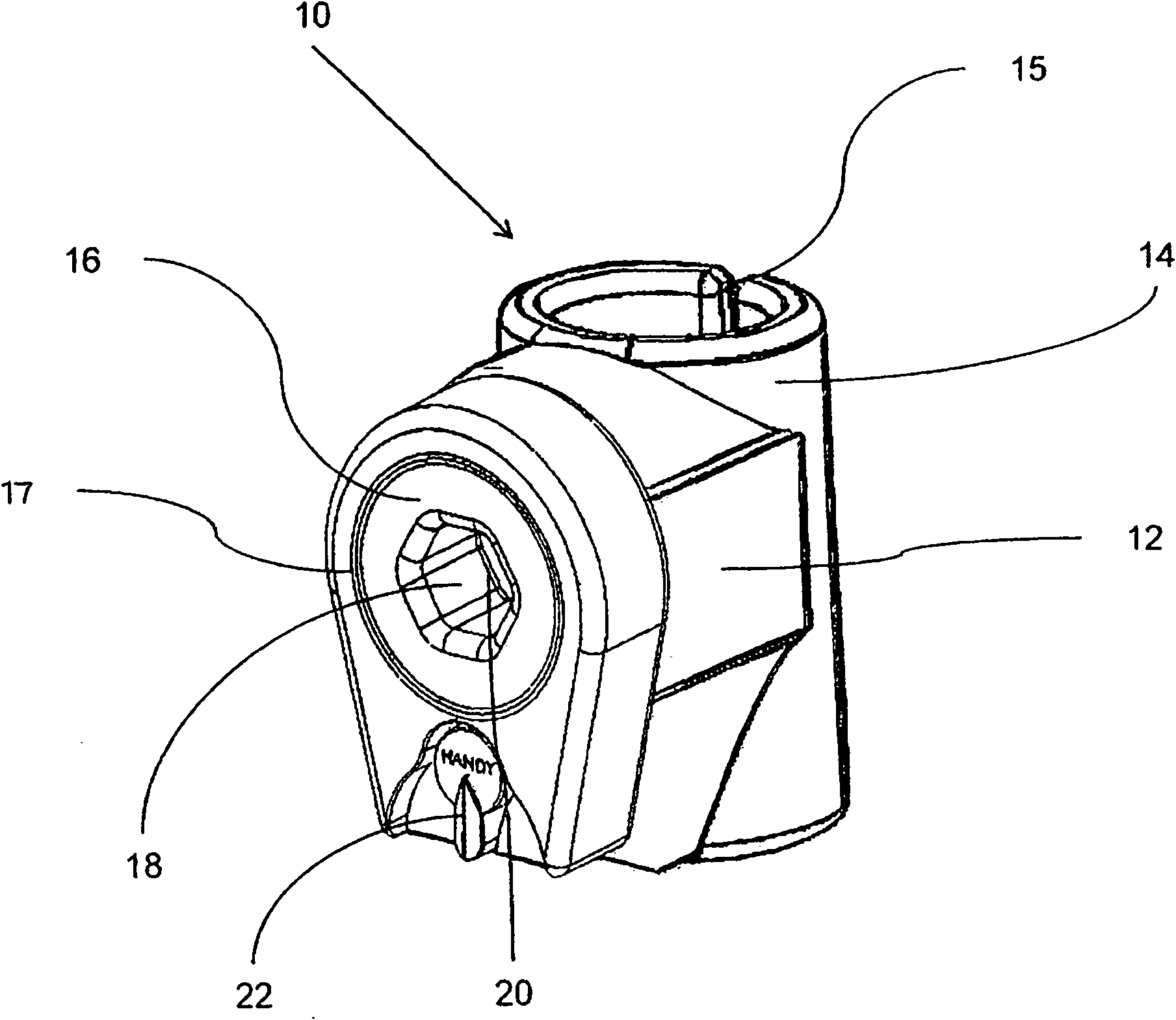
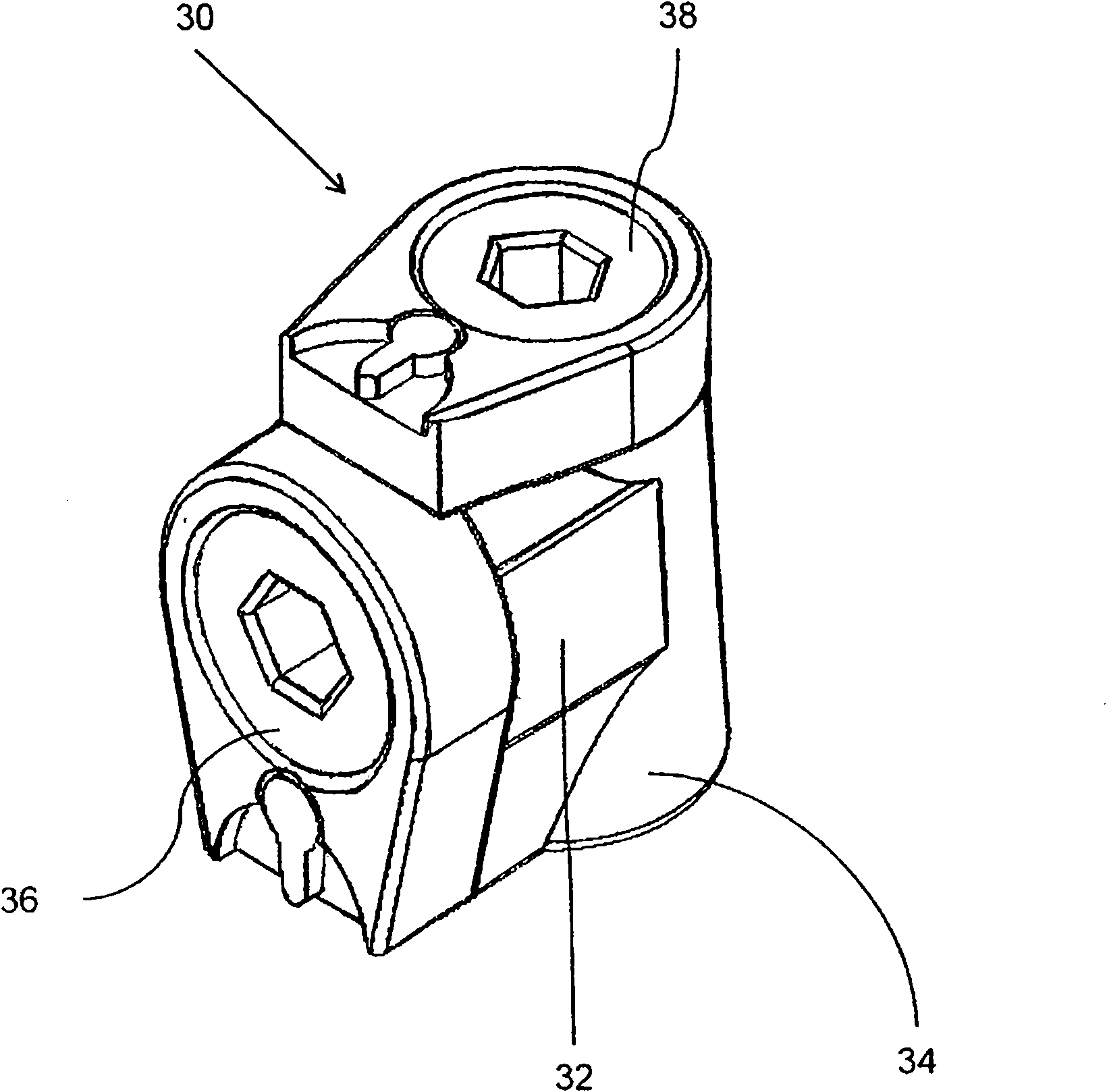
[0025] The invention relates to a tool holder for holding a tool by means of magnets, comprising a finger cot allowing the tool holder to be mounted on a fingertip for handling a tool bit or other accessory. The tool holder includes a finger cot and a tool holding part connected with the finger cot. The tool holder is formed at least partially from a magnetic material. The magnetic tool holder may include a bit wrench for holding a tool bit, such as a screw bit, socket bit, or the like. In another embodiment, the magnetic tool holder can hold accessories such as flashlights, knives, pens, clips or small mirrors for use in hard to reach places. For purposes of this application, the term "tool" in relation to tool holders refers to any hardware tool and accessory, including screw heads, socket heads, wrenches, component holders, and the like, or accessories of various kinds, such as flashlights, Laser tags, small mirrors, knives and more.

[0026] According to another embodim...


PUM


Abstract

The invention relates to a tool maintainer, which is used for maintaining a tool by using a magnetic body. The tool maintainer comprises a finger cot and a tool maintaining part which is connected with the finger cot, wherein the finger cot is used for making the maintainer mounted on a finger tip, so that a tool head or other accessories are convenient to operate; and at least part of the tool maintaining part is made of magnetic materials. Preferably, a magnetic tool maintainer can comprise a head spanner, a socket spanner, a screw head or an element maintainer.

Description

technical field [0001] The present application relates generally to tool holders, and in particular to tool holders for holding and manipulating at fingertips. Background technique [0002] Finger-mounted tools and tool holders are well known in the prior art for use in difficult-to-access areas. US Patent No. 2,585,641 to Faso relates to a tool, such as a wrench, screwdriver, etc., that includes a ferrule for mounting on top of the finger. US Patent No. 6,834,570 to Risolio relates to a finger wrench that can be used to reach places only fingers can reach. [0003] Terpinski's US patent application US2006 / 0185057 relates to a magnetic glove that facilitates holding, mounting and retrieving small metal objects such as nuts or screws in hard-to-reach places. [0004] Accordingly, there remains a need for a tool holder for holding and manipulating machine tools, and it is desirable to have a tool holder that securely holds a finger-mounted tool. Contents of the invention ...

Claims


Application Information

Patent Timeline
IPC IPC(8): B25G1/10
Inventor A·米勒
Owner 波莱尔斯解决方案有限公司
Learn More