
Air conditioner

A technology for changing blades of air conditioners and wind direction, which is applied to airflow control components, mechanical equipment, etc., which can solve problems such as discomfort, and achieve the effect of improving comfort, energy saving, and efficient air conditioning

Inactive Publication Date: 2011-11-09
PANASONIC INTELLECTUAL PROPERTY MANAGEMENT CO LTD
View PDF5 Cites 18 Cited by
  • Summary
  • Abstract
  • Description
  • Claims
  • Application Information

AI Technical Summary

Problems solved by technology

Therefore, especially when there is a large amount of air flow or when the blowing temperature is lowered not only during heating but also during cooling, the blown air cannot be turned horizontally only by changing the vertical direction of the airflow, and the blown air can be turned downward rather than horizontally. Direction of blowing, so there is a problem that the blowing wind directly contacts the occupants and brings discomfort

Method used


Image

  • Air conditioner
  • Air conditioner
  • Air conditioner

Examples


Embodiment approach 1

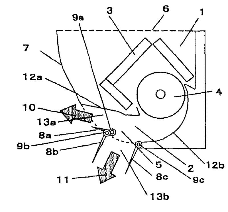
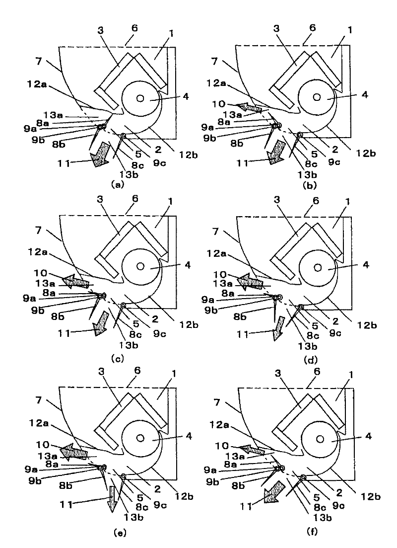
[0049] figure 1 A cross-sectional view showing the air conditioner in operation. In the figure, the air conditioner 1 includes a heat exchanger 3 and a blower fan 4 for circulating blown air indoors in its main body. Heat exchanger 3 is arranged on the upstream side of blower fan 4 . In addition, the air conditioner 1 is equipped with a suction port 6 for sucking indoor air on the main body top surface side, an air outlet 5 arranged near the lower part of the main body front side from the front part of the main body bottom surface side, and blows out air-conditioned air. The front panel 7 on the upper part of the air outlet 5 on the front side.

[0050] The blower passage 2 from the blower fan 4 to the air outlet 5 is constituted by an upper wall surface 12a and a lower wall surface 12b formed on the main body. The upper wall surface 12a is formed substantially horizontally or even upward toward the downstream direction of the air flow.

[0051] The air outlet 5 is provid...


PUM


Abstract

The invention provides an air conditioner, which adjusts strength and wind direction of hot air and cold air toward a residential area, provides comfortable cold and warm environment for every one, and realizes whole circulation of hot air and cold air in a living room with high efficiency and excellent energy-saving performance. The air conditioner is provided with three upper-lower air direction changing blades making upper-lower air direction changeable, wherein the first and the second upper-lower air changing blades are configured in a mode that the end parts are roughly close to each other between upper end and lower end of an air outlet, and the third upper-lower air changing blade is configured in a mode that an end part is made to be roughly close to the lower end of the air outlet.

Description

technical field [0001] The invention relates to a device for adjusting the vertical wind direction in an air conditioner. Background technique [0002] At present, there is an air conditioner [for example, refer to Patent Document 1]. Figure 6 As described in (a) or (b), two blades for changing the vertical air direction are arranged independently and freely rotatably above and below the air outlet. Figure 6 (a) shows the state of the up and down wind direction changing blades when the heating operation heats up, Figure 6 (b) shows the state of the up and down wind direction changing blades when the heating operation is stable. Figure 6 In (a), both of the blades 15a, 15b for changing the up and down wind direction are adjusted to be inclined downward in the forward direction, so that the hot air is completely blown downward. In addition, Figure 6 In (b), the up and down wind direction changing vane 15a above the air outlet is adjusted to be as close as possible to a hori...

Claims


Application Information

Patent Timeline
Patent Type & Authority Applications(China)
IPC IPC(8): F24F13/14F24F11/76
Inventor 井上雄二田积欣公米泽胜
Owner PANASONIC INTELLECTUAL PROPERTY MANAGEMENT CO LTD
Learn More