Fly tapper

A technology for traps and flies, which is applied in the field of fly traps, and can solve the problems of unsightly placement and low trapping efficiency

Inactive Publication Date: 2011-11-23
陈迪芳
View PDF5 Cites 1 Cited by
  • Summary
  • Abstract
  • Description
  • Claims
  • Application Information

AI Technical Summary

Problems solved by technology

The structure of this patent is simple, but in practical application, because the slit can only accommodate flies, the flies will escape during the process o

Method used


Image

  • Fly tapper
  • Fly tapper
  • Fly tapper

Examples


Embodiment Construction

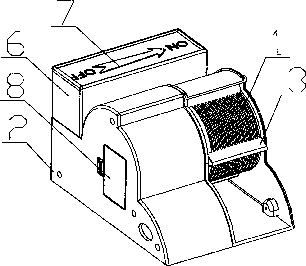
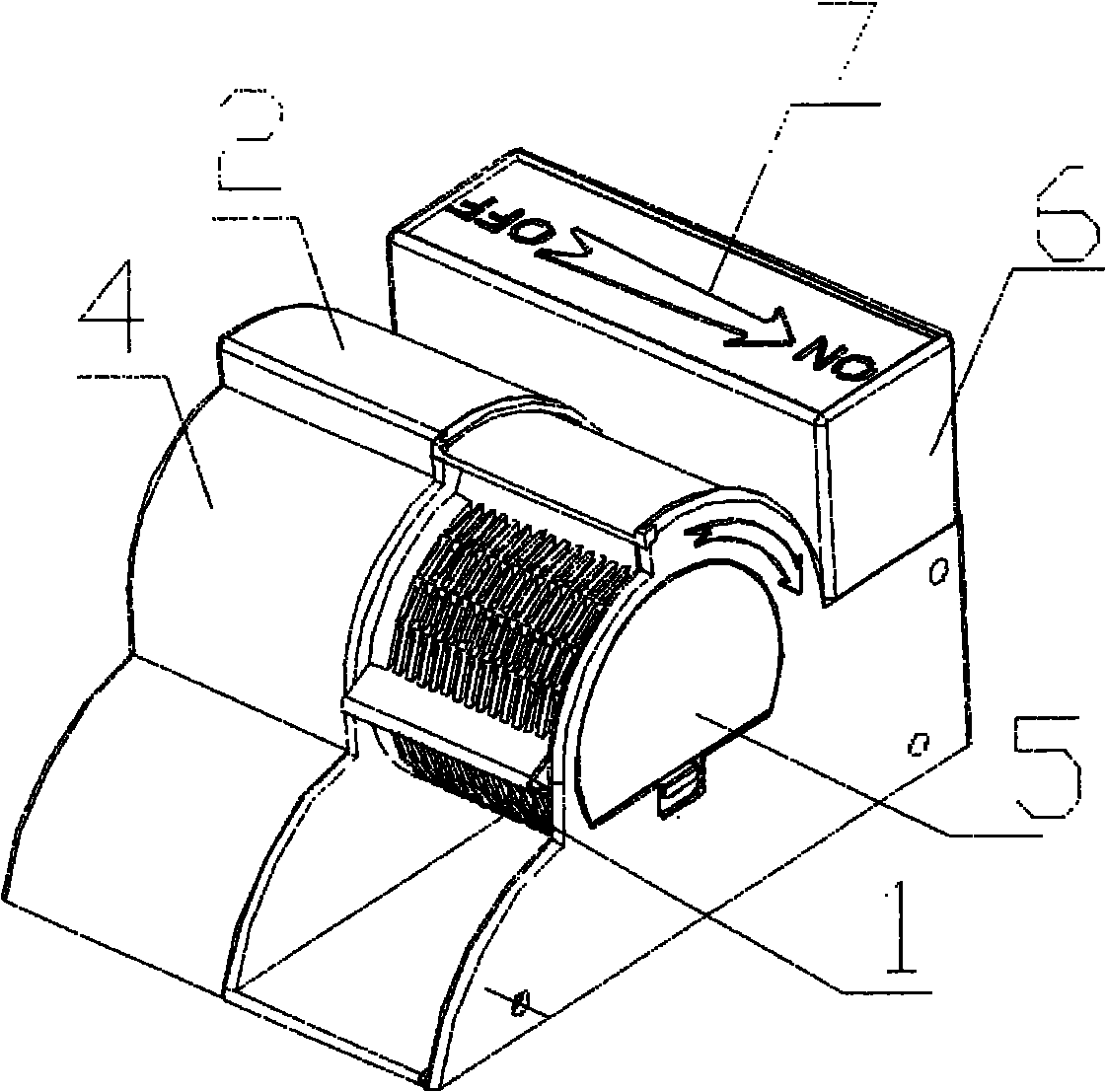
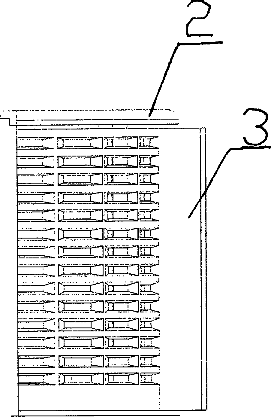
[0016] Such as figure 1 , figure 2 as well as image 3 As shown, the fly trap of the present invention includes a body 2, a DC motor 4 is installed in the body 2, and the DC motor 4 is connected to the drum device 1 through a rotator. The drum device 1 is provided with a bait drawer 5, and the rear of the body 2 is installed There is a fly storage chamber 6 connected to the drum device 1. The body 2 has a clock shape. Fly blocking baffles 3 are uniformly arranged on the drum device 1. A sliding opening 7 is provided on the fly storage room 6.

[0017] When working, it is necessary to first place bait in the bait drawer 5. The bait is usually fish, meat and other easily found foods. The smell of the bait attracts the flies. After smelling the flies, the flies climb on the drum device 1, and the spinner drives the drum device 1 to rotate slowly, and the flies are slowly swept into the fly storage chamber 6 without knowing it. Since the bait is placed in the bait drawer 5, the ...


PUM


Abstract

The invention aims to provide a fly trapper which is of a reasonable and simple structure, saves energy and labor, can effectively trap and deal with flies and has beautiful appearance to be perfectly placed in house. To achieve the effects, the fly trapper comprises a body, wherein a DC (direct current) motor is arranged in the body and connected with a roller device through a rotator; a bait drawer is arranged on the roller device; and a fly storage room connected to the roller device is arranged on the rear side of the body. Due to the technical scheme, the fly trapper traps flies through the bait drawer arranged on the roller device, and rolls up the flies in the fly storage room. As the fly is attracted by the bait in the bait drawer, distance from the body is large in the roll-up process so that the fly does not become careful and escape; and even if the fly wants to escape, the fly is blocked by a rotating fly baffle, and thus the catching effect of the fly trapper is ensured.

Description

Technical field [0001] The invention relates to a trap, in particular to a fly trap. Background technique [0002] Flies are the first of the four pests, which constantly harass people's daily life and infect bacteria. What's more hateful is that its reproductive ability is so strong that it cannot be eradicated. In this regard, there are also a variety of fly-killing products on the market, ranging from traditional fly swatters and fly papers to advanced fly-repellent devices and ultraviolet lamps. There are also pros and cons between various anti-fly products. Traditional flies removal products have average effects and require people to actively search for flies. Even if the flies are knocked down, the subsequent handling is very troublesome. The advanced fly-repellent device and the ultraviolet lamp occupies a large area, which consumes energy and high maintenance costs. Moreover, the appearance is relatively obtrusive, and it is not very beautiful when placed indoors. In...

Claims


Application Information

Patent Timeline
IPC IPC(8): A01M1/10
Inventor 陈迪芳
Owner 陈迪芳
Why Eureka
Try Eureka