Particulate filter and cylinder body structure for GIS/GIL

A particle trap and cylinder technology, which is applied in the directions of electrostatic cleaning, cleaning methods and utensils, chemical instruments and methods, etc. Particle cleaning and other problems, to achieve the effect of simplifying the structure, high efficiency, and ensuring the capture efficiency

Active Publication Date: 2020-11-20
PINGGAO GRP +2
View PDF14 Cites 6 Cited by
  • Summary
  • Abstract
  • Description
  • Claims
  • Application Information

AI Technical Summary

Problems solved by technology

[0005] The purpose of the present invention is to provide a particle catcher to solve the technical problem that the particle catcher in the prior art is located inside the cylinder, which is inconvenient for the disassembly and assembly of the particle catcher and the cleaning of metal particles; the purpose of the present invention is also to provide A cylinder structure for GIS / GIL, in order to solve the technical problems in the prior art that the particulate trap is located inside the cylinder, which is inconvenient for the disassembly and assembly of the particulate trap and the cleaning of metal particles

Method used


Image

  • Particulate filter and cylinder body structure for GIS/GIL
  • Particulate filter and cylinder body structure for GIS/GIL
  • Particulate filter and cylinder body structure for GIS/GIL

Examples


specific Embodiment 1

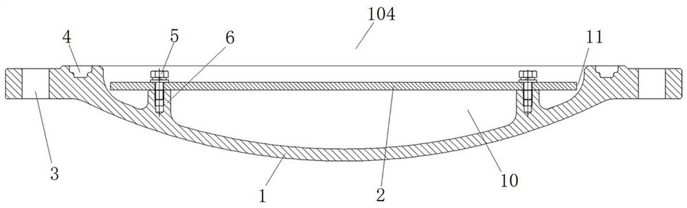
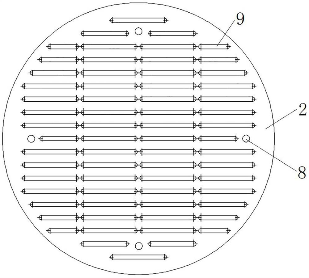
[0067] Such as figure 1 As shown, the particle trap 104 includes a trap cover plate 1 and a trap grid plate 2, and the trap grid plate 2 is detachably connected to the trap cover plate 1 to form a trap between the trap grid plate 2 and the trap cover plate 1. Potential area; e.g. image 3 As shown, grid holes 9 are evenly distributed on the trap grid plate 2, and the grid holes 9 allow metal particles to pass through so that the metal particles enter the equipotential region 10, thereby realizing the capture of the metal particles.

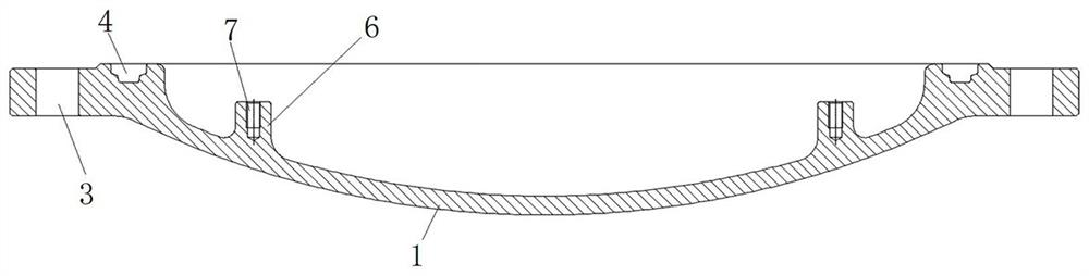
[0068] Such as figure 2 As shown, the side of the trap cover plate 1 facing the trap grid plate 2 is provided with a convex portion 6, and the convex portion 6 is provided with a threaded hole 7, and the opening of the threaded hole 7 faces the trap grid plate 2, wherein the threaded hole 7 is along the There are four evenly distributed circumferentially of the trap cover plate 1 .

[0069] Such as image 3 As shown, the trap grid plate 2 is ...

specific Embodiment 2

[0081] The difference from the specific embodiment 1 is that in embodiment 1, the trap grid plate 2 is a flat plate, the trap cover plate 1 is a spherical cap structure, and an equipotential area is formed between the trap grid plate 2 and the trap cover plate 1. For example, such as Figure 6 As shown, the particle trap 204 includes a trap cover plate 21 and a trap grid plate 22, the trap cover plate 21 is a spherical cap structure, the middle part of the trap grid plate 22 protrudes upwards, and its edge is provided with a fixed flange 23, and the trap grid plate The grid plate 22 is fixedly connected to the trap cover plate 21 through the cooperation of the fixed flange 23 and the fastening screw 24 , and a larger equipotential area is formed between the trap grid plate 22 and the trap cover plate 21 . In other embodiments, the trap cover 21 may be a flat plate.

[0082] In this embodiment, an application of the particulate trap 204 is as Figure 7 As shown, the cylinder ...

specific Embodiment 3

[0084] The difference from the specific embodiment 1 is that in embodiment 1, the trap grid plate 2 is a flat plate, the trap cover plate 1 is a spherical cap structure, and an equipotential area is formed between the trap grid plate 2 and the trap cover plate 1. For example, such as Figure 8 As shown, the middle part of the trap grid plate 32 protrudes downwards, and its edge is provided with a fixed flange 33, and the trap grid plate 32 is fixedly connected to the trap cover plate 31 through the fixed flange 33 and the fastening screw 34, and the trap A smaller equipotential area is formed between the grid plate 32 and the trap cover plate 31 .


PUM


Abstract

The invention relates to a particulate filter and a cylinder body structure for GIS/GIL. The particulate filter comprises a trap cover plate and a trap grid plate; a cover plate connecting structure is arranged on the trap cover plate, the trap cover plate is used for being detachably and fixedly connected to the opening of the cylinder wall of a cylinder body through the cover plate connecting structure; and the trap grid plate is detachably connected to the trap cover plate so that an equipotential area can be formed between the trap grid plate and the trap cover plate, grid holes are distributed in the trap grid plate, and the grid holes allow metal particulates to pass through so that the metal particulates can enter the equipotential area. After the trap cover plate is fixedly connected to the corresponding cylinder body, under the action of alternating-current high voltage, the metal particulates in the cylinder body can move under the action of an electric field and finally passthrough the grid holes to enter the equipotential area, so that the metal particulates are not affected by the electric field any more, the metal particulates stop moving, and capturing of the metalparticulates is achieved; moreover, the trap cover plate and the trap grid plate are both of plate-shaped structures, so that the structure of the particulate filter is simplified.

Description

technical field [0001] The invention relates to a particle trap and a cylinder structure for GIS / GIL. Background technique [0002] GIS products generally utilize SF 6 Gas insulation, and metal particles will inevitably be generated inside the GIS. The reasons for the generation are: the residue of metal particles generated during the assembly process, the metal particles generated by the wear of the moving contact during operation, and the wear of the conductive rod caused by thermal expansion and contraction. Produced metal particles, etc. Due to the violent movement of metal particles under the action of AC high voltage, the insulation performance of GIS will be reduced, resulting in discharge accidents. [0003] The Chinese patent with the application publication number CN110883016A discloses a GIL device, which includes a cylinder body in which a particle trap is arranged. The particle trap is a cylindrical structure coaxially arranged with the cylinder body. There i...

Claims


Application Information

Patent Timeline
Patent Type & Authority Applications(China)
IPC IPC(8): B08B6/00
CPCB08B6/00
Inventor 占小猛柴影辉段晓辉魏建巍董祥渊谢世超高远井琼琼张银穗孙英杰杜迎乾贺永明苏士伟张振宋航宇徐锦举崔江红
Owner PINGGAO GRP
Why Eureka
Try Eureka