Particle trap and cylinder structure for gis/gil
A particle trap and cylinder technology, which is applied in the directions of electrostatic cleaning, cleaning methods and utensils, chemical instruments and methods, etc. Particle cleaning and other issues to achieve the effect of simplifying the structure and ensuring the capture efficiency
- Summary
- Abstract
- Description
- Claims
- Application Information
AI Technical Summary
Problems solved by technology
Method used
Image
Examples
specific Embodiment 1
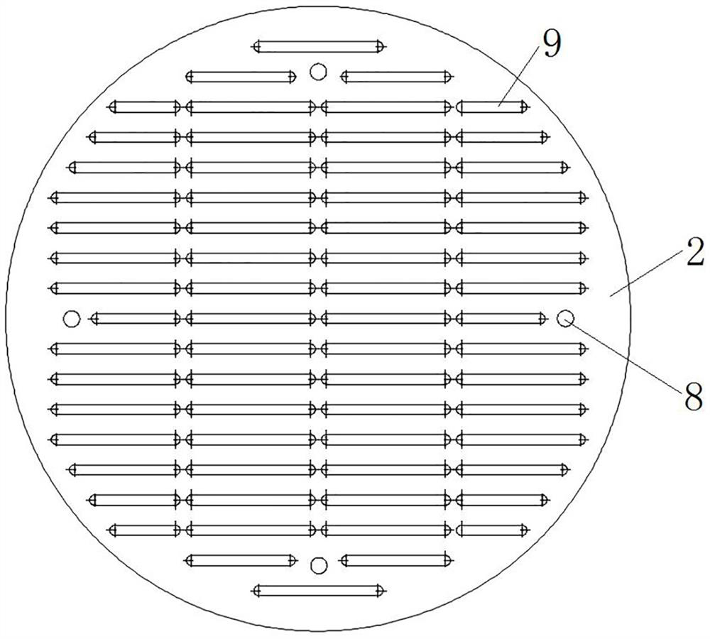
[0067] Such as figure 1 As shown, the particle trap 104 includes a trap cover plate 1 and a trap grid plate 2, and the trap grid plate 2 is detachably connected to the trap cover plate 1 to form a trap between the trap grid plate 2 and the trap cover plate 1. Potential area; e.g. image 3 As shown, grid holes 9 are evenly distributed on the trap grid plate 2, and the grid holes 9 allow metal particles to pass through so that the metal particles enter the equipotential region 10, thereby realizing the capture of the metal particles.
[0068] Such as figure 2 As shown, the side of the trap cover plate 1 facing the trap grid plate 2 is provided with a convex portion 6, and the convex portion 6 is provided with a threaded hole 7, and the opening of the threaded hole 7 faces the trap grid plate 2, wherein the threaded hole 7 is along the There are four evenly distributed circumferentially of the trap cover plate 1 .
[0069] Such as image 3 As shown, the trap grid plate 2 is ...
specific Embodiment 2
[0081] The difference from the specific embodiment 1 is that in embodiment 1, the trap grid plate 2 is a flat plate, the trap cover plate 1 is a spherical cap structure, and an equipotential area is formed between the trap grid plate 2 and the trap cover plate 1. For example, such as Figure 6 As shown, the particle trap 204 includes a trap cover plate 21 and a trap grid plate 22, the trap cover plate 21 is a spherical cap structure, the middle part of the trap grid plate 22 protrudes upwards, and its edge is provided with a fixed flange 23, and the trap grid plate The grid plate 22 is fixedly connected to the trap cover plate 21 through the cooperation of the fixed flange 23 and the fastening screw 24 , and a larger equipotential area is formed between the trap grid plate 22 and the trap cover plate 21 . In other embodiments, the trap cover 21 may be a flat plate.
[0082] In this embodiment, an application of the particulate trap 204 is as Figure 7 As shown, the cylinder ...
specific Embodiment 3
[0084] The difference from the specific embodiment 1 is that in embodiment 1, the trap grid plate 2 is a flat plate, the trap cover plate 1 is a spherical cap structure, and an equipotential area is formed between the trap grid plate 2 and the trap cover plate 1. For example, such as Figure 8 As shown, the middle part of the trap grid plate 32 protrudes downwards, and its edge is provided with a fixed flange 33, and the trap grid plate 32 is fixedly connected to the trap cover plate 31 through the fixed flange 33 and the fastening screw 34, and the trap A small equipotential area is formed between the grid plate 32 and the trap cover plate 31 .
PUM
 Abstract
Description
Claims
Application Information
 - R&D
- Intellectual Property
- Life Sciences
- Materials
- Tech Scout
- Unparalleled Data Quality
- Higher Quality Content
- 60% Fewer Hallucinations
Browse by: Latest US Patents, China's latest patents, Technical Efficacy Thesaurus, Application Domain, Technology Topic, Popular Technical Reports.
© 2025 PatSnap. All rights reserved.Legal|Privacy policy|Modern Slavery Act Transparency Statement|Sitemap|About US| Contact US: help@patsnap.com


