
Ball spinning forming tooling device and reverse ball spinning forming method thereof

A ball and shape technology, applied in the field of ball spinning forming tooling device and its reverse ball spinning forming, to achieve the effect of simple tooling, light equipment and small deformation area

Inactive Publication Date: 2011-12-07
HARBIN ENG UNIV
View PDF3 Cites 22 Cited by
  • Summary
  • Abstract
  • Description
  • Claims
  • Application Information

AI Technical Summary

Problems solved by technology

Although the above process methods have their own advantages, they all have certain limitations in processing high-strength, high-precision thin-walled cylindrical parts with longitudinal inner ribs.

Method used


Image

  • Ball spinning forming tooling device and reverse ball spinning forming method thereof
  • Ball spinning forming tooling device and reverse ball spinning forming method thereof
  • Ball spinning forming tooling device and reverse ball spinning forming method thereof

Examples


Embodiment Construction

[0028] The present invention is described in more detail below in conjunction with accompanying drawing example:

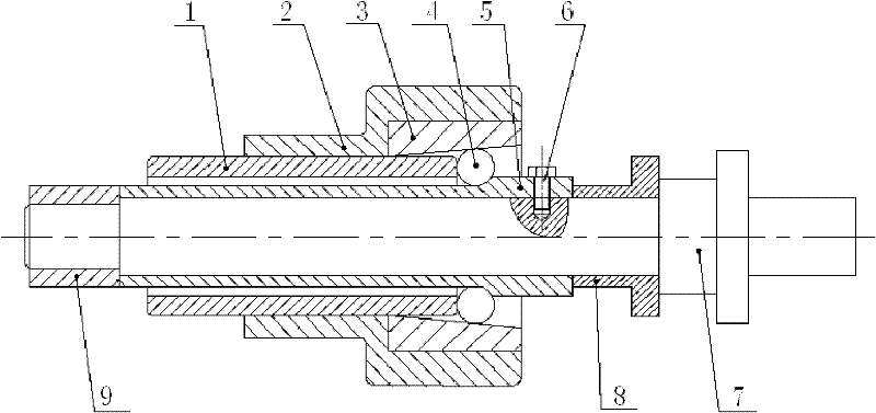
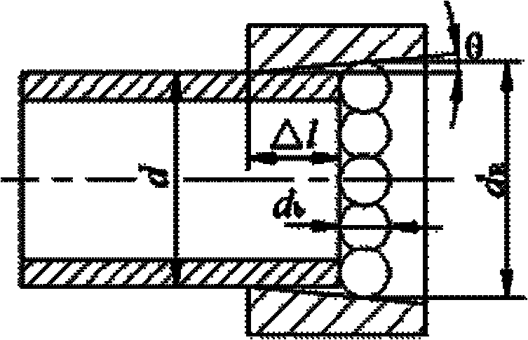
[0029] combine Figure 1-7 , Ball spinning forming process scheme Ball spinning is carried out on a common lathe, the spinning head in the ball spinning tooling is clamped on the main shaft of the lathe, and the mandrel with the blank is installed on the tail top of the lathe, The spinning head rotates at high speed with the spindle of the lathe, and the core mold with the blank is fed axially with the tail top of the lathe, and the axial flow of the blank on the core mold is restricted, which is conducive to filling the inner ribs.

[0030] Ball spinning tooling structure The tooling includes three parts: spinning head, mandrel and restraint device, such as figure 1 shown.

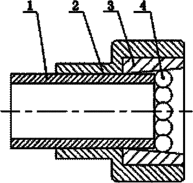
[0031] The spinning head part is composed of threaded support tube 1, outer support ring 2, conical die ring 3 and ball 4, such as figure 2 . The outer surface of the threaded support pi...


PUM


Abstract

The object of the present invention is to provide a ball spinning forming tooling device and its reverse ball spinning forming method. The ball spinning forming tooling device includes a spinning head, a mandrel and a limit ring. The spinning head includes a threaded support tube, an outer support Ring, conical die ring, balls, threaded support tube and conical die ring are installed in the outer support ring, one end of the threaded support tube is located in the conical die ring, the balls are located in the conical die ring, and are evenly distributed around the conical surface of the conical die ring , and in contact with the threaded support pipe, the core mold includes a mandrel and a discharge ring, the discharge ring is sleeved on the mandrel, and the limit ring is sleeved on one end of the mandrel. The reverse ball spinning forming method is completed through three steps: preparation stage, spinning stage and unloading stage. The invention can manufacture high-strength, high-precision thin-walled longitudinal internal rib cylindrical parts. The radial position of the tooling ball can be precisely controlled by adjusting the threaded support tube, which greatly improves the forming accuracy.

Description

technical field [0001] The invention relates to a mechanical part forming device and a forming method thereof. Background technique [0002] Cylindrical parts with longitudinal inner ribs are widely used in industrial fields such as civil, shipbuilding, aviation and aerospace. On the one hand, cylindrical parts with longitudinal inner ribs are to meet the needs of structural design. Generally, cylindrical parts have higher strength, higher rigidity, good heat dissipation and stable vibration characteristics. The traditional processes for processing cylindrical parts with longitudinal inner ribs mainly include extrusion forming, machining after casting pre-forming, machining after forging pre-forming and chemical corrosion. Although the above process methods have their own advantages, they all have certain limitations in processing high-strength, high-precision thin-walled cylindrical parts with longitudinal inner ribs. With the rapid development of powerful spinning techno...

Claims


Application Information

Patent Timeline
IPC IPC(8): B21D22/16
Inventor 江树勇张艳秋佟永祥范红涛
Owner HARBIN ENG UNIV
Learn More