Cap sorter

A technology of cap arranging machines and capping bins, applied in the field of cap arranging machines, can solve the problems of low efficiency of manual cap arranging and inability to arrange special-shaped bottle caps, etc., and achieve the effect of improving the efficiency of cap arranging

Inactive Publication Date: 2011-12-14
GUANGZHOU TECH LONG PACKAGING MACHINERY CO LTD
View PDF5 Cites 17 Cited by
  • Summary
  • Abstract
  • Description
  • Claims
  • Application Information

AI Technical Summary

Problems solved by technology

[0004] But the existing cap unscrambling machine can only unscramble ordinary bottle caps (such as the cap whose height dimension is smaller than its outer diameter), and for the special-shaped bottle cap whose height dimension is larger than its outer diameter size, and the outer wall of the bottle cap has a ring shape. The special-shaped caps at the ears cannot be sorted accurately, because the shoulders of the cap unscrambler can only effectively block the reverse caps (caps with the caps facing downwards), and when the caps are facing horizontally with the caps When entering the cap selection area in the same way, the bottle cap whose height dimension is larger than the outer diameter can also enter the cap capacity area through the cap selection area, and the special-shaped cap with ring-shaped ears on the outer wall of the bottle cap will partially enter the cap capacity area, and due to its ear The part is stuck between the cap selection area and the cap capacity area, so these special-shaped bottle caps cannot be sorted accurately. For this reason, the existing technology still uses manual sorting of these bottle caps, and the efficiency of the way of man-made caps Low

Method used


Image

  • Cap sorter
  • Cap sorter
  • Cap sorter

Examples


Embodiment Construction

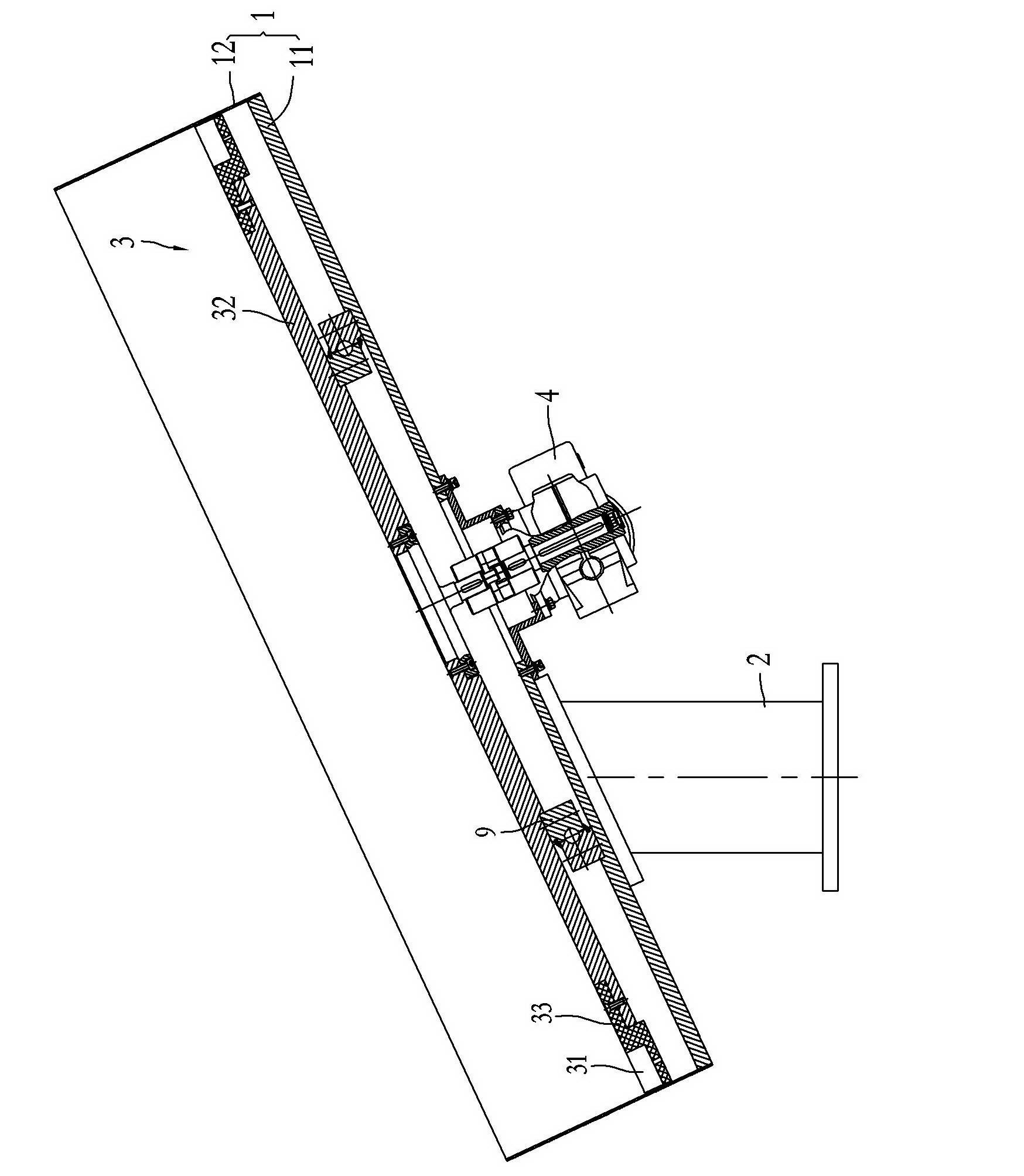
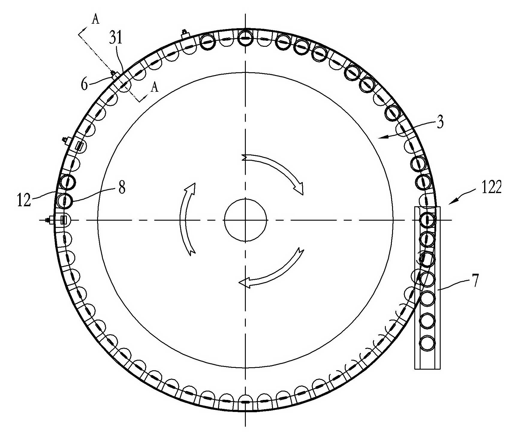
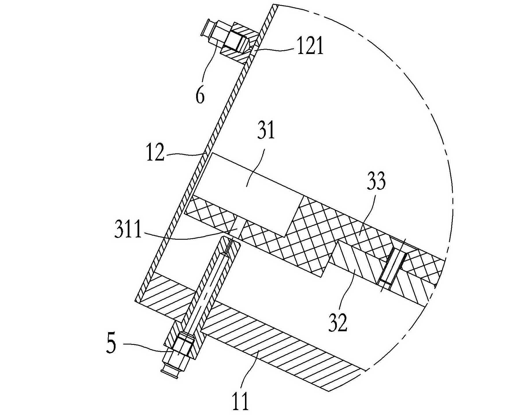
[0012] Such as Figures 1 to 6 As shown, a cover sorting machine according to the present invention includes a cover bin 1 obliquely installed on the support 2. The cover bin 1 includes a bottom plate 11 and a coaming plate 12 fixed on the outer edge of the bottom plate 11. The inside of the cover bin 1 corresponds to There is an inclined turntable 3 above the bottom plate 11, and a transmission device 4 for driving the inclined turntable 3 to rotate is installed on the bottom plate 11. A plurality of accommodating grooves 31 are distributed on the edge of the inclined turntable 3, and the accommodating grooves The width and length of 31 are slightly larger than the outer diameter of bottle cap 8, and the accommodating groove 31 is evenly distributed along the edge of the inclined turntable. The position is fixed with a bottom blowing nozzle 5, and the bottom blowing nozzle 5 is connected to an external air compression device (not shown in the figure). The distance between th...


PUM


Abstract

The invention discloses a cap sorter, which comprises a cap bin obliquely arranged on a support. An oblique turntable is arranged on the inner side of the cap bin corresponding to the upper side of a bottom plate of the cap bin; the bottom plate is provided with a transmission device used for driving the oblique turntable to rotate; a plurality of accommodating grooves are distributed on the edge of the oblique turntable; the bottom walls of the accommodating grooves are provided with through holes; a bottom blowing air tap is fixed on the bottom plate corresponding to path lines of the through holes; a coaming of the cap bin is provided with a compressed air inlet corresponding to the upper sides of the accommodating grooves; a distance between the compressed air inlet and the bottom surfaces of the accommodating grooves is slightly longer than the height of a bottle cap; the outside of the compressed air inlet is provided with a side blowing air tap; the upper side of the coaming is provided with a bottle cap outlet corresponding to the tangential direction of the path of the accommodating grooves; and the bottle cap outlet is provided with a slideway used for conveying the bottle cap from the cap bin. By utilizing the Venturi principle, the cap sorter can sort common bottle caps, special bottle caps of which the height is greater than the outer diameter, and special caps of which the outer walls are provided with annular lugs, and the cap sorting efficiency is greatly improved.

Description

technical field [0001] The invention relates to a cover sorting machine. Background technique [0002] On the production line of bottled products (such as bottled beverages), when the filling machine fills a predetermined amount of material into the bottle, it needs to be capped. In order to improve production efficiency, the existing technology uses a capping machine to cap the bottle, and the messy bottle caps need to be sorted out in the capping process. [0003] The existing common bottle cap (such as crown cap) cap unscrambling machine mainly selects the bottle cap with the cap facing upward (positive cap) through the cap selection area, and blocks the cap with the cap not facing upward outside the cap selection area. In order to achieve the purpose of Ligai. For example, the Chinese patent application number "200420062717.0" discloses "a crown cover sorting machine". When the lower turntable and the cover ring rotate under the drive of the transmission device, the co...

Claims


Application Information

Patent Timeline
Patent Type & Authority Applications(China)
IPC IPC(8): B67B3/00B65G47/24
Inventor 樊缔王波李正良
Owner GUANGZHOU TECH LONG PACKAGING MACHINERY CO LTD
Why Eureka
Try Eureka