sealing ring
A sealing ring and non-sealing technology, applied in the direction of engine sealing, engine components, mechanical equipment, etc., can solve the problem of small design freedom
- Summary
- Abstract
- Description
- Claims
- Application Information
AI Technical Summary
Problems solved by technology
Method used
Image
Examples
Embodiment 1
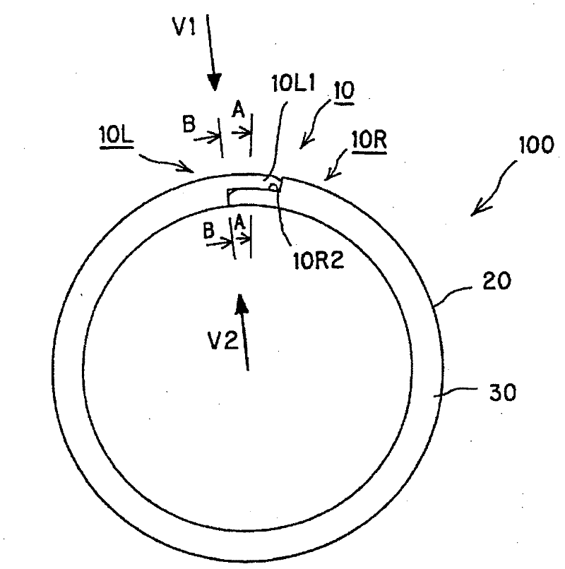
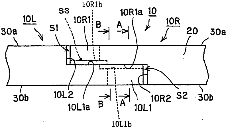
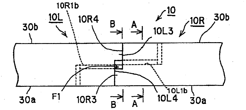
[0104] refer to Figure 1 to Figure 10 , to illustrate the sealing ring of Embodiment 1 of the present invention.
[0105]
[0106] refer to figure 1 , illustrating the overall structure of the sealing ring in Embodiment 1 of the present invention. figure 1 It is a side view of the sealing ring of Embodiment 1 of the present invention.
[0107] The sealing ring 100 of this embodiment is installed in the annular groove 201 provided on the rotating shaft 200 , and the rotating shaft 200 is inserted into the shaft hole of the shaft sleeve 300 . The sealing ring 100 is in free sliding contact with the side wall surface of the non-sealed fluid side (A) of the annular groove 201, and is in contact with the inner peripheral surface of the shaft hole of the shaft sleeve 300, and the ring shape between the above-mentioned rotating shaft 200 and the shaft hole Gap seal to prevent leakage of sealing fluid oil on the sealing fluid side (O) (see Figure 9 and Figure 10 ). Furthe...
Embodiment 2
[0142] refer to Figure 11 ~ Figure 20 A seal ring according to a second embodiment of the present invention will be described.
[0143]
[0144] refer to Figure 11 The overall structure of the sealing ring of the second embodiment of the present invention will be described. Figure 11 It is a side view of the sealing ring of the second embodiment of the present invention.
[0145] The sealing ring 100X of this embodiment is installed in the annular groove 201X provided on the rotating shaft 200X, and the rotating shaft 200X is inserted into the shaft hole of the shaft sleeve 300X. The sealing ring 100X is in slidable contact with the side wall surface of the non-sealed fluid side (A) of the annular groove 201X, and is in contact with the inner peripheral surface of the shaft hole of the shaft sleeve 300X. Gap seal to prevent leakage of sealing fluid oil on the sealing fluid side (O) (see Figure 19 and Figure 20 ). Furthermore, the seal ring 100X of this embodiment ...
PUM
 Abstract
Description
Claims
Application Information
 - R&D
- Intellectual Property
- Life Sciences
- Materials
- Tech Scout
- Unparalleled Data Quality
- Higher Quality Content
- 60% Fewer Hallucinations
Browse by: Latest US Patents, China's latest patents, Technical Efficacy Thesaurus, Application Domain, Technology Topic, Popular Technical Reports.
© 2025 PatSnap. All rights reserved.Legal|Privacy policy|Modern Slavery Act Transparency Statement|Sitemap|About US| Contact US: help@patsnap.com


