
Condenser

A condenser and refrigerant technology, which is applied in the direction of evaporator/condenser, refrigerator, refrigeration components, etc., can solve the problems of wasted space in the engine room, large space in the condenser, insufficient gas-liquid separation performance, etc., and achieve space saving , good effect

Inactive Publication Date: 2011-11-09
KEIHIN THERMAL TECH CORP
View PDF7 Cites 12 Cited by
  • Summary
  • Abstract
  • Description
  • Claims
  • Application Information

AI Technical Summary

Problems solved by technology

[0004] In the condenser described in the above publication, in order to effectively separate the gas and liquid in the first liquid collecting tank, it is necessary to make the inner volume of the first liquid collecting tank considerably larger than that of the second liquid collecting tank, so the first set The thickness of the liquid tank is considerably larger than that of the second liquid collecting tank, so there is a problem that a large space is required for arranging the condenser
[0005] In addition, other equipment is usually arranged near the condenser, but according to the condenser described in the above publication, the first liquid collection tank becomes an obstacle to other equipment.
For example, a radiator is usually arranged on the downstream side of the ventilation direction of the condenser for automobile air conditioners, but according to the condenser described in the publication, the first liquid collecting tank will become an obstacle to the installation of the radiator, and wasteful waste will be generated in the engine room. space, no space savings
In addition, since the heat exchange tube is connected to the first liquid collecting tank substantially in the entire length, there is a problem that the gas-liquid separation performance is insufficient.

Method used


Image

  • Condenser
  • Condenser
  • Condenser

Examples


Embodiment Construction

[0031] Hereinafter, embodiments of the present invention will be described with reference to the drawings.

[0032] In the description below, the figure 1 The inside of the paper ( Figure 4 The upper side) is the front, and the opposite side is the back.

[0033] In addition, in the following description, the term "aluminum" includes not only pure aluminum but also aluminum alloys.

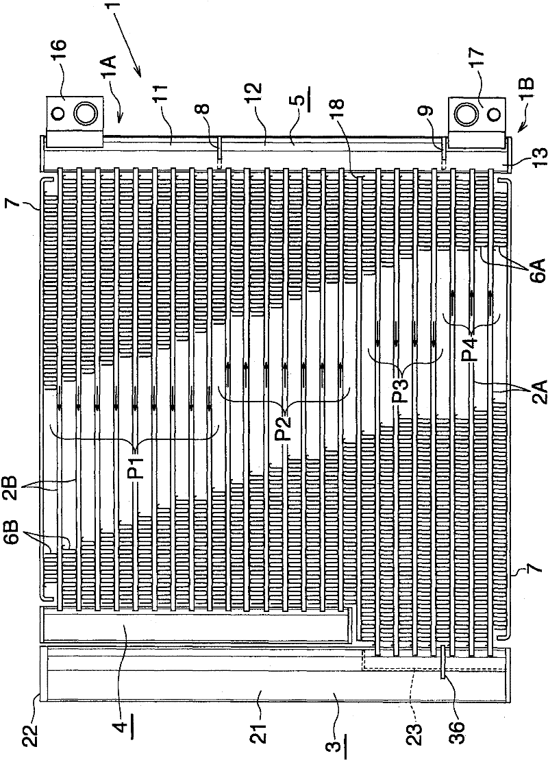
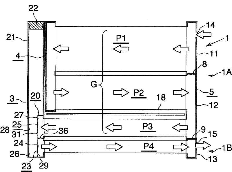
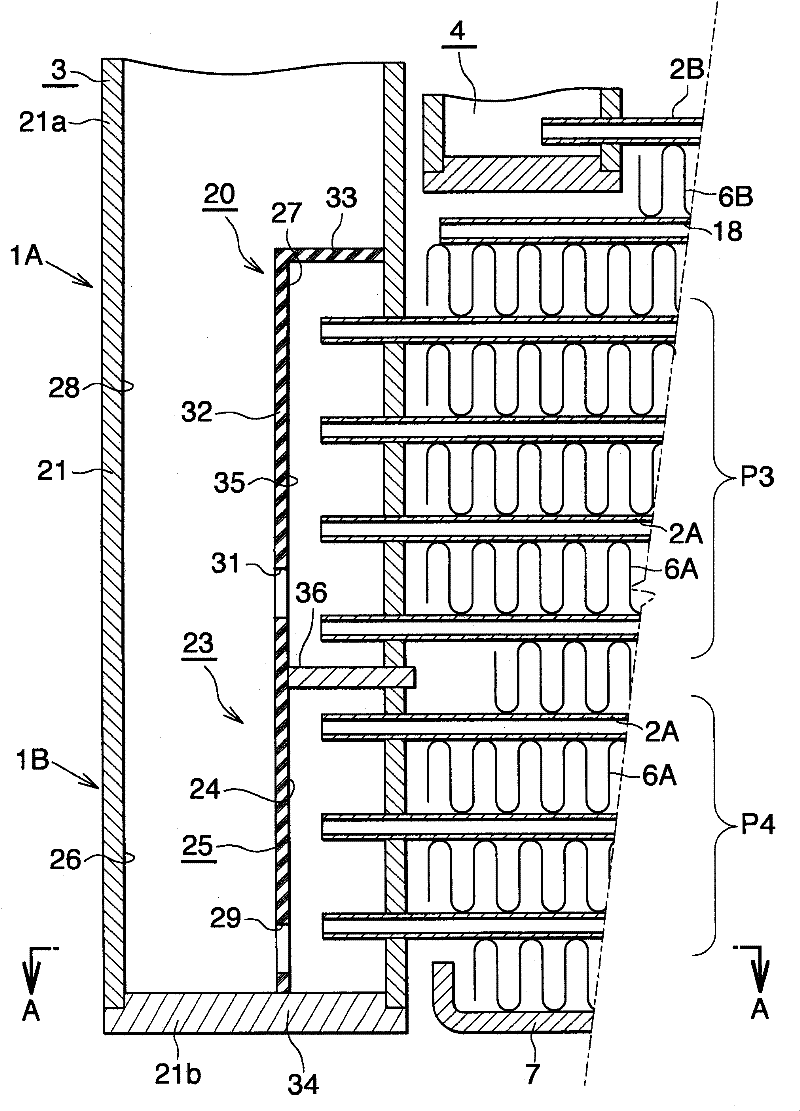
[0034] figure 1 Concretely showing the overall structure of the first embodiment of the condenser of the present invention, figure 2 Schematically express figure 1 the condenser. exist figure 2 In FIG. 2 , the illustration of each heat exchange tube is omitted, and the illustration of corrugated fins, side plates, refrigerant inlet parts, and refrigerant outlet parts is also omitted. in addition, image 3 and Figure 4 express figure 1 The structure of the main part of the condenser.

[0035] exist figure 1 and figure 2 Among them, the condenser 1 has: a plurality of aluminum flat...


PUM


Abstract

The invention provides a condenser, which is suitable for an automobile air conditioner mounted on an automobile. The one end part side of a condenser (1) is provided with: a first liquid collecting box (3) connected with a first heat exchange pipe (2A) of a third heat exchange passage way and a fourth heat exchange passage way (P3, P4); a second liquid collecting box (2B) connected with a second heat exchange pipe (2B) of a first heat exchange passage way and a second heat exchange passage way (P1, P2), The upper end of the first liquid collecting box is located above the lower end of the second liquid collecting box. The first liquid collecting box has a shunting control mechanism (23) promoting a liquid phrase refrigerant to flow from the internal of the first liquid collecting box to the first heat exchange pipe of the fourth heat exchange passage way. The shunting control mechanism is provided with a spatial forming part (25), which forms a sealed refrigerant inflow space (24) communicating the fourth heat exchange passage way and the first heat exchange pipe, and a liquid accumulating space (26) at the external side of the refrigerant inflow space. The space forming part is provided with a communicating part (29) communicating the lower side part of the refrigerant inflow space and the liquid accumulating space.

Description

technical field [0001] The present invention relates to a condenser suitable for use in, for example, a refrigerating cycle mounted on an automobile, that is, an automobile air conditioner. Background technique [0002] In this specification and claims, up and down, left and right refer to figure 1 Up and down, left and right. [0003] For example, as a condenser for an automobile air conditioner, there is known a condenser having a plurality of heat exchange tubes arranged in parallel at intervals in the vertical direction, and a tube extending in the vertical direction connected to the left and right ends of the heat exchange tubes. There are three heat exchange passages composed of a plurality of heat exchange tubes arranged in parallel up and down, and the refrigerant flow direction of all the heat exchange tubes constituting each heat exchange passage is the same and adjacent to each other. The refrigerant flow directions of the heat exchange tubes of the two heat exc...

Claims


Application Information

Patent Timeline
IPC IPC(8): F25B39/04F28F9/02
CPCF28D2021/0084F28F9/0209F28F9/0268F28F2009/029F28D1/05375
Inventor 鸨崎和美藤井隆行濑野善彦铃木新吾
Owner KEIHIN THERMAL TECH CORP
Learn More