Method and device for detecting power battery insulation resistance of electric automobile

A technology of insulation resistance and power battery, applied in measuring devices, measuring resistance/reactance/impedance, measuring electricity, etc., can solve the problem of inability to locate the leakage position, and achieve the effect of eliminating inaccurate detection.

Active Publication Date: 2014-07-23
QIMING INFORMATION TECH +1
View PDF2 Cites 0 Cited by
  • Summary
  • Abstract
  • Description
  • Claims
  • Application Information

AI Technical Summary

Problems solved by technology

[0003] The invention discloses a method for detecting the insulation resistance of a power battery of an electric vehicle, which can determine the current leakage state of the power battery through the variation of the insulation resistance sampling voltage, and solves the problem that the traditional insulation resistance detection cannot locate the leakage position

Method used


Image

  • Method and device for detecting power battery insulation resistance of electric automobile
  • Method and device for detecting power battery insulation resistance of electric automobile

Examples


Embodiment 1

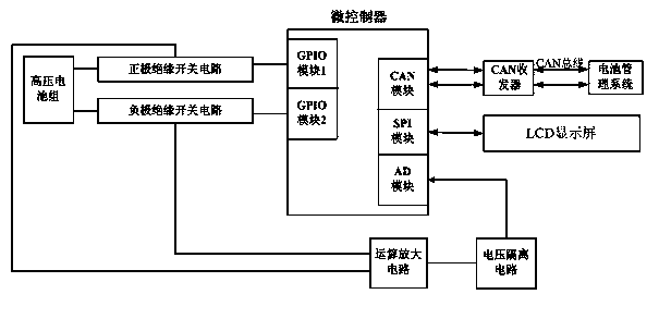
[0034] Such as figure 1 Shown: The power battery insulation resistance detection device is mainly composed of a microcontroller (MCU-Micro Control Unit), a positive insulation switch circuit, a negative insulation switch circuit, an operational amplifier circuit, a voltage isolation circuit, and a CAN-Controller Area Network. ) Transceiver and LCD display. Among them, the GPIO-General Purpose Input Output (GPIO-General Purpose Input Output) module 1 of the MCU is externally connected to the control terminal of the positive insulated optocoupler relay, and the GPIO module 2 of the MCU is connected to the control terminal of the negative insulated optocoupler relay. Select the conduction logic to output the insulation resistance sampling voltage. After the insulation resistance sampling voltage is processed by the operational amplifier circuit, it enters the voltage isolation circuit for voltage isolation processing. Finally, input to the analog-to-digital conversion (AD-Anal...

Embodiment 2

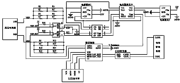
[0036] Such as figure 2As shown: the positive insulation switch circuit is mainly composed of a positive voltage divider circuit and a positive insulation optocoupler relay. When the control terminal VHP_KEY of the positive insulation optocoupler relay outputs a low level, a path is formed between pin 1 and pin 2 of the relay, so that pin 7 and pin 8 of the relay are turned on, and resistors R0~R7 and R16 form a positive voltage divider circuit. Pin 7 outputs a positive insulation resistance sampling voltage value.

[0037] The negative pole insulation switch circuit is mainly composed of a negative pole voltage divider circuit and a negative pole insulation optocoupler relay. When the control terminal VHN_KEY of the negative insulation optocoupler relay outputs a low level, a path is formed between pin 3 and pin 4 of the relay, so that pin 5 and pin 6 of the relay are turned on, and resistors R8~R15 and R17 form a negative voltage divider circuit. Pin 6 outputs a negativ...


PUM


Abstract

The invention relates to a power battery insulation resistance detection method and device for an electric vehicle. The two general-purpose input / output interfaces of a micro-controller are respectively connected to positive and negative insulation switch circuits, and the positive and negative insulation switch relays are selected to output the insulation resistance sampling voltage. . The sampling voltage passes through the operational amplifier circuit, and after being isolated by the voltage isolation chip, it is input to the analog-to-digital conversion unit of the microcontroller. The microcontroller calculates the insulation resistance value of the current power battery according to the algorithm, and sends it to the battery management system in the form of a message by the communication module for use by the battery management system. The invention effectively solves the problem that the traditional insulation resistance detection device cannot judge whether it is positive leakage, negative leakage or double leakage simultaneously. It can accurately measure the leakage degree of the current power battery. Eliminate potential safety hazards caused by inaccurate insulation resistance testing.

Description

technical field [0001] The invention discloses a method for detecting the insulation resistance of a power battery of an electric vehicle, and also provides a device for realizing the method, belonging to the field of new energy electric vehicles. Background technique [0002] The energy of electric vehicles mainly comes from the on-board power battery. Since the power battery is generally more than several hundred volts, if an accidental leakage occurs, it will directly threaten personal safety. Therefore, electric vehicles need a device that can detect the insulation resistance of power batteries in real time. At the same time, an excellent power battery insulation resistance detection method is also the most important performance index for evaluating an electric vehicle. The traditional power battery insulation resistance detection method can only determine whether the current power battery is in a leakage state, but cannot determine whether the power battery is leaking...

Claims


Application Information

Patent Timeline
Patent Type & Authority Patents(China)
IPC IPC(8): G01R27/02G01R31/36
Inventor 吴畏朱庆林姜鹏董冰黄敏
Owner QIMING INFORMATION TECH
Why Eureka
Try Eureka