Image processing method and image processing device

An image processing and image technology, applied in the direction of image data processing, image enhancement, image analysis, etc., can solve problems such as inapplicable images, and achieve the effect of reducing the impact

Inactive Publication Date: 2011-12-28
PANASONIC CORP
View PDF5 Cites 26 Cited by
  • Summary
  • Abstract
  • Description
  • Claims
  • Application Information

AI Technical Summary

Problems solved by technology

Therefore, specular correction is also specific to the camera system and cannot be applied to images captured by other systems

Method used


Image

  • Image processing method and image processing device
  • Image processing method and image processing device
  • Image processing method and image processing device

Examples


Embodiment approach 1

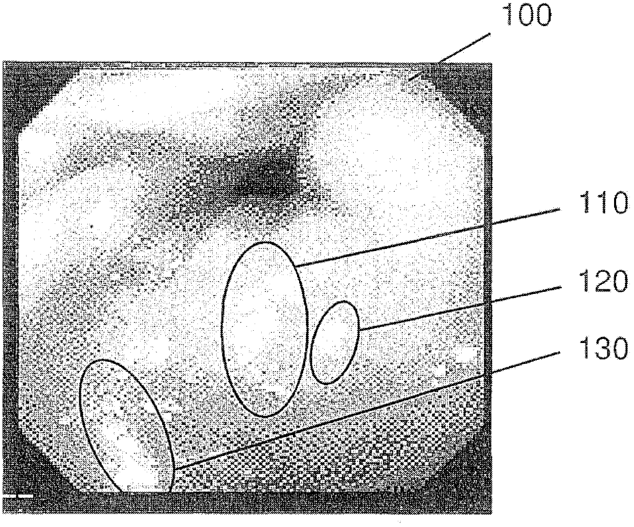
[0066] figure 1 is an example of an image 100 captured using an endoscope inspection apparatus (endoscope). As can be seen from image 100, the somewhat smaller saturated image areas of these portions of areas 110, 120 and 130 are formed by specular reflection. Therefore, no valid information exists at the location of the specular reflection.

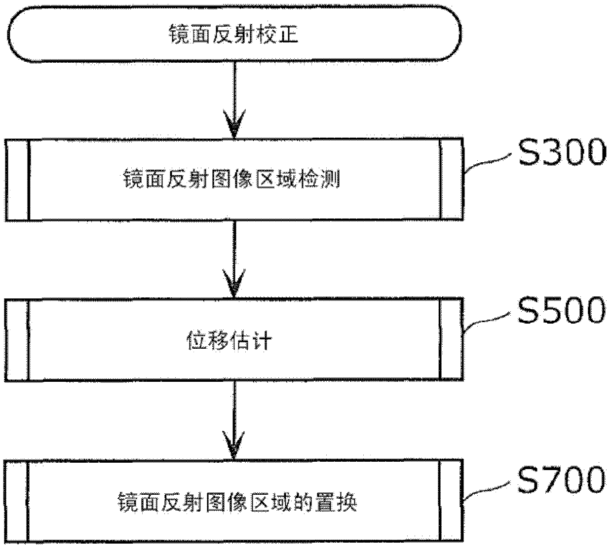
[0067] figure 2 It is a flowchart of a method for detecting and reducing specular reflection in a captured video sequence of the present invention. In the specular reflection reduction method of the present invention, first, a specular reflection area in a captured image is detected (S300). In subsequent S500, another image or a plurality of images is searched for an area corresponding to an image area covered by specular reflection in the captured image. Finally, the specular reflection in the captured image is replaced with information from a single or multiple images (S700). Here, the image to be searched is an image of another ...

Embodiment approach 2

[0157] In Embodiment 1, a specular reflection area is targeted for replacement, while in Embodiment 2, a saturated area, which is an image area where pixel values ​​are saturated, and a false color area located around the saturated area are targeted for replacement. The false color area refers to an area in which a blue false color is generated around the saturated pixel value.

[0158] In addition, in the following description, the content different from Embodiment 1 will be mainly described, and the description of the same process will be omitted suitably.

[0159] The image to be processed in Embodiment 2 is a color image composed of RGB components, YUV components, or YCbCr components.

[0160] Figure 13 It is a block diagram showing the configuration of an image processing device according to Embodiment 2 of the present invention.

[0161] The image processing device according to Embodiment 2 includes a saturated area detection unit 2501 , a false color area detection u...

Embodiment approach 3

[0190] In Embodiment 2, the interpolation of the false color area is performed using pixel values ​​in the same image. In contrast, in the third embodiment, the interpolation of the false color area is performed using pixel values ​​in other images.

[0191] In addition, in the following description, the content different from Embodiment 1 and 2 will be mainly described, and the description of the same process will be omitted suitably.

[0192] The image to be processed in Embodiment 3 is a color image composed of RGB components, YUV components, or YCbCr components.

[0193] Figure 22 It is a block diagram showing the configuration of an image processing device according to Embodiment 3 of the present invention.

[0194] The image processing device according to Embodiment 3 includes a saturated area detection unit 2601 , a false color area detection unit 2602 , a displacement estimator 2603 , and a replacement unit 2604 .

[0195]The saturated area detection unit 2601 dete...


PUM


Abstract

An image processing method and an image processing device. The image processing device includes: a specular reflection detector (1110) for detecting, in the first image, an enlarged area including a saturated area and an adjacent area, where the saturated area is a pixel area with a pixel value equal to or greater than a predetermined threshold, and the adjacent area is at least partially an area surrounding the saturated area; and a replacement unit (1130) for using the enlargement in the second image for pixel values ​​of pixels included in at least an adjacent area of ​​the enlarged area detected by the specular reflection detector (1110) The pixel value of the pixel at the corresponding position of the region or the pixel value of the adjacent pixel at the corresponding position is replaced.

Description

technical field [0001] The present invention relates to an image processing method and an image processing device for correcting a region where pixel values ​​are saturated or a region where false colors are generated. Background technique [0002] In various uses of imaging, bright spots (glare spots) may occur in captured images due to the influence of specular reflection. Such bright spots make the composition of the captured scene unclear, resulting in reduced visibility of the captured image. [0003] Considering a bright spot in such a captured image as a pixel value, its value is saturated. For example, when each pixel of a grayscale image is represented by 8 bits, the pixel value can take a value from 0 to 255, but the bright spot is 255 or a value close thereto. [0004] In camera processing, the sensor captures the light reflected from the scene being photographed. In general, the term "light" does not necessarily refer to light in the visible range, but may be ...

Claims


Application Information

Patent Timeline
Patent Type & Authority Applications(China)
IPC IPC(8): H04N5/243H04N5/232
CPCG06T5/005G06T5/50G06T2207/10068
Inventor T·韦迪F·尼克T·帕尔夫纳S·维特曼
Owner PANASONIC CORP
Why Eureka
Try Eureka