
Dual-groove shuttle track double-weave circular weaving machine

A circular loom, double groove technology, applied in circular looms, looms, textiles, etc., can solve the problems of large labor workload, broken wires, low efficiency, etc., achieve stable and reliable operation, and improve labor productivity. , to avoid the effect of breakage

Inactive Publication Date: 2012-01-04
黄美昌 +1
View PDF0 Cites 0 Cited by
  • Summary
  • Abstract
  • Description
  • Claims
  • Application Information

AI Technical Summary

Problems solved by technology

[0002] At present, the plastic circular looms manufactured, sold and used at home and abroad all use a single-cone structure for the running track of the shuttle boat. One circular loom can only weave one plastic woven bag, and the warp thread for weaving passes between the upper and lower door circles. , when the shuttle boat moves on the running track, relying on the centrifugal force of the shuttle boat when it makes a circular motion along the upper and lower door rings, the four shuttle wheels are pressed against the single-cone track on the upper and lower door rings for rolling contact motion. This structure is used for weaving. In the actual use of plastic woven bags, there are often shuttle failures and failures caused by the shuttle wheel rolling many warp threads, which seriously affects the normal production, heavy labor workload and low efficiency.

Method used


Image

  • Dual-groove shuttle track double-weave circular weaving machine
  • Dual-groove shuttle track double-weave circular weaving machine
  • Dual-groove shuttle track double-weave circular weaving machine

Examples


Embodiment Construction

[0009] Embodiments are further described in detail below in conjunction with accompanying drawings

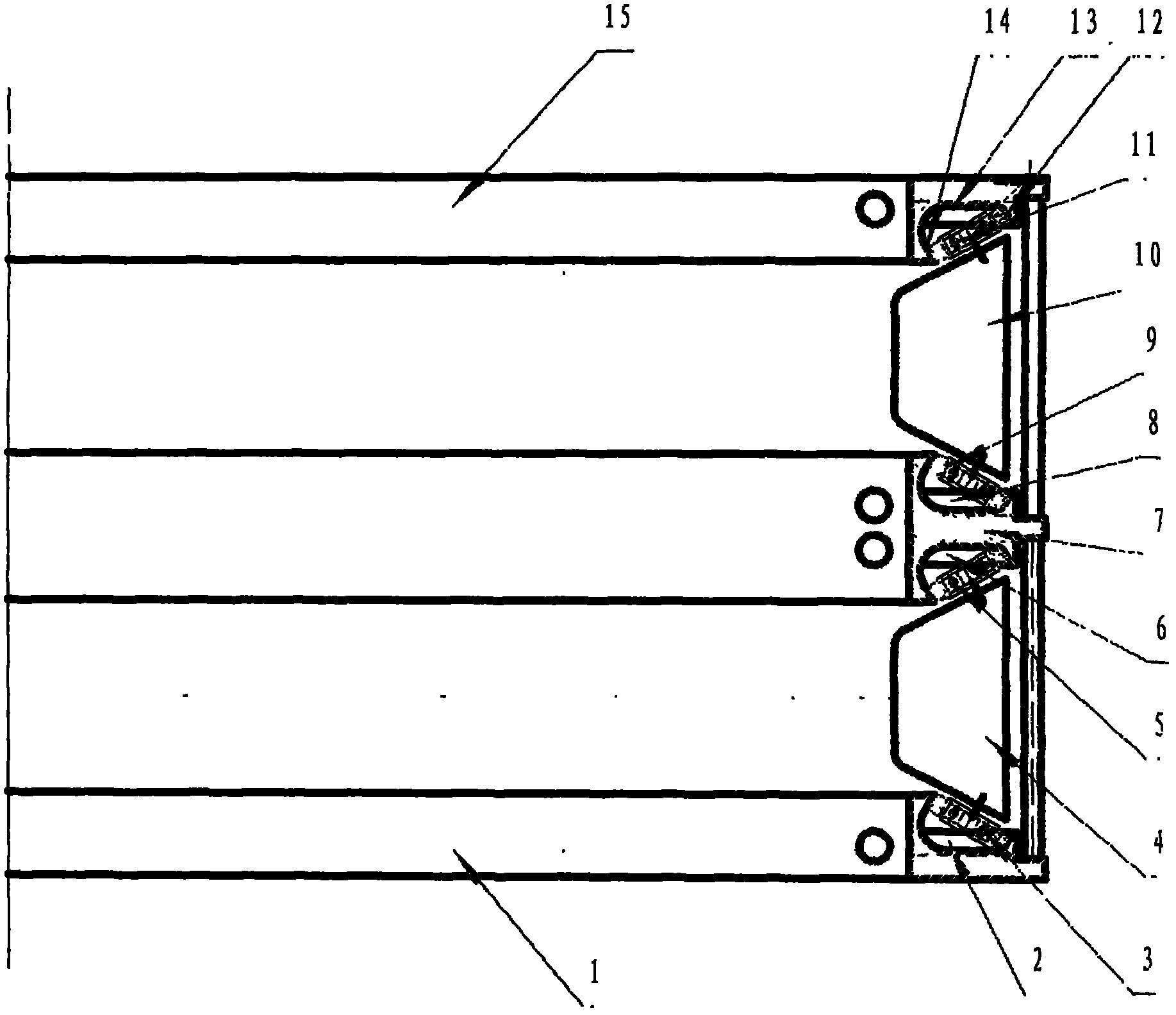
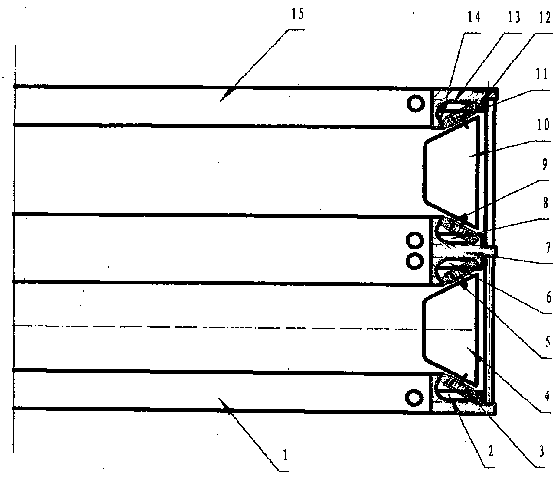
[0010] refer to figure 1 : 1-lower door ring, 2-lower door ring groove, 3-lower shuttle boat lower shuttle wheel, 4-lower shuttle boat, 5-lower shuttle boat upper shuttle wheel, 6-middle door ring lower groove, 7-middle Door ring, 8-the upper groove of the middle door ring, 9-the lower shuttle wheel of the upper shuttle boat, 10-the upper shuttle boat, 11-the upper shuttle wheel of the upper shuttle boat, 12-the outer groove wall of the groove, 13-the upper door ring groove, 14-groove inner groove wall, 15-upper door circle, a double-groove shuttle boat track double weaving circular loom, including lower door circle 1, lower shuttle boat 4, middle door circle 7, upper shuttle boat 10, upper door circle Ring 15, the upper edge of the lower door ring 1 is designed with a groove 2, the lower edge of the middle door ring 7 is designed with a groove 6, the upper edge of the middle ...


PUM


Abstract

The invention discloses a dual-groove shuttle track double-weave circular weaving machine. A host comprises a lower door ring, a lower shuttle, a middle door ring, an upper shuttle and an upper door ring, wherein two layers of shuttles and a dual-groove track structure are arranged on the upper, middle and lower door rings; the outer walls of the grooves of the upper, middle and lower door rings bear the centrifugal force during the circular motion of the shuttles, and the lower walls of the grooves of the upper, middle and lower door rings effectively prevent the shuttle flying; and when the host runs, the weaving warps on the upper layer pass through multiple radial thread slots on the upper edges of the upper and middle door rings, and the weaving warps on the lower layer pass through multiple radial thread slots on the lower edge of the middle door ring and the upper edge of the lower door ring. The weaving warps are protected from the rolling of shuttle wheels, and the failure of warp crack and breakage is avoided; one weaving machine can weave two plastic woven bags at the same time, the operation is stable and reliable, and the labor productivity is improved by over 50%.

Description

technical field [0001] The invention relates to the field of plastic circular looms, in particular to a double-groove shuttle track double-loom circular loom. technical background [0002] At present, the plastic circular looms manufactured, sold and used at home and abroad all use a single-cone structure for the running track of the shuttle boat. One circular loom can only weave one plastic woven bag, and the warp thread for weaving passes between the upper and lower door circles. , when the shuttle boat moves on the running track, relying on the centrifugal force of the shuttle boat when it makes a circular motion along the upper and lower door rings, the four shuttle wheels are pressed against the single-cone track on the upper and lower door rings for rolling contact motion. This structure is used for weaving. In the actual use of plastic woven bags, there are often shuttle failures and the failure of the shuttle wheel to cause cracks and broken wires due to the rolling ...

Claims


Application Information

Patent Timeline
Patent Type & Authority Applications(China)
IPC IPC(8): D03D37/00
Inventor 黄美昌黄加宁
Owner 黄美昌
Learn More