
Shuttle ship and running orbit structure of plastic circular weaving machine

A technology of circular looms and shuttle boats, applied to circular looms, looms, textiles, etc., can solve the problems of many wearing parts, high noise, high power consumption, etc., to reduce noise, reduce wearing parts, and reduce costs Effect

Inactive Publication Date: 2010-08-18
黄美昌 +2
View PDF5 Cites 7 Cited by
  • Summary
  • Abstract
  • Description
  • Claims
  • Application Information

AI Technical Summary

Problems solved by technology

[0002] At present, there are four types of shuttle boats and running track structures that use plastic circular looms at home and abroad. One is to rely on 4 shuttle wheels on the shuttle boat to run on the tapered runway of the upper and lower door circles; The 4 shuttle wheels run on the flat stepped runway of the upper and lower door rings, and the anti-flying shuttle relies on the shuttle bottom plate to slide and rub on the gate track between the upper and lower door rings; The anti-flying shuttle runs on the flat stepped runway of the door ring, relying on the shuttle bottom plate to run on the roller track between the upper and lower door rings; the fourth type uses 4 shuttle wheels on the shuttle boat to run on the upper and lower door ring flat stepped runway The anti-flying shuttle runs on the top, relying on the 3-4 rollers at the bottom of the shuttle to run on the gate track between the upper and lower door rings; these 4 types of structures have different degrees of broken wires, flying shuttles, loud noises, and fragile Defects such as many parts and high power consumption

Method used


Image

  • Shuttle ship and running orbit structure of plastic circular weaving machine
  • Shuttle ship and running orbit structure of plastic circular weaving machine
  • Shuttle ship and running orbit structure of plastic circular weaving machine

Examples


Embodiment Construction

[0016] Further detailed description embodiment below in conjunction with accompanying drawing

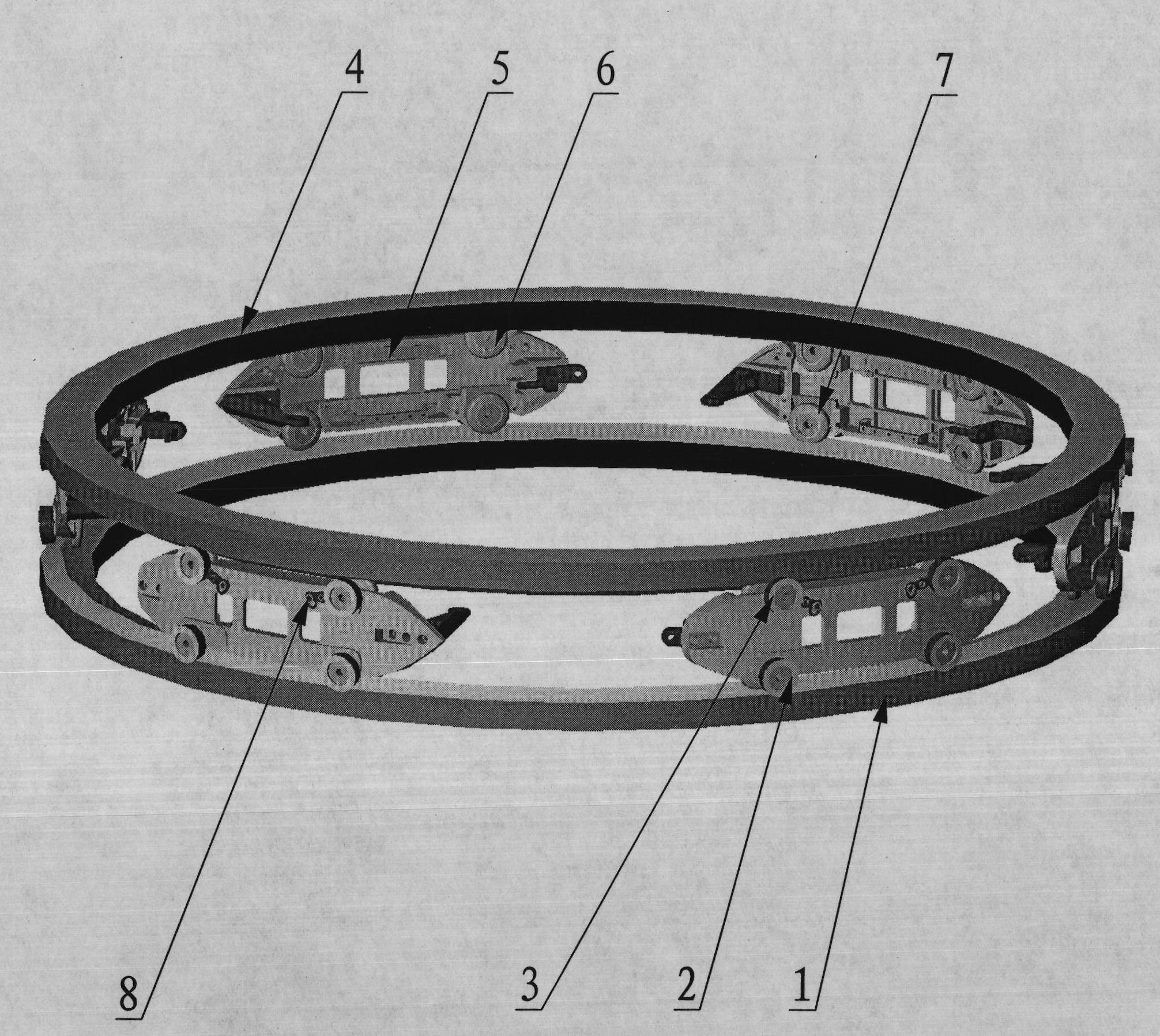
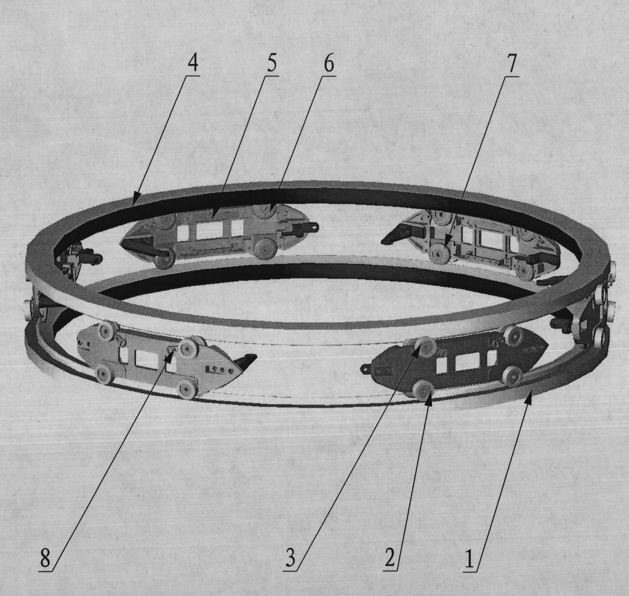
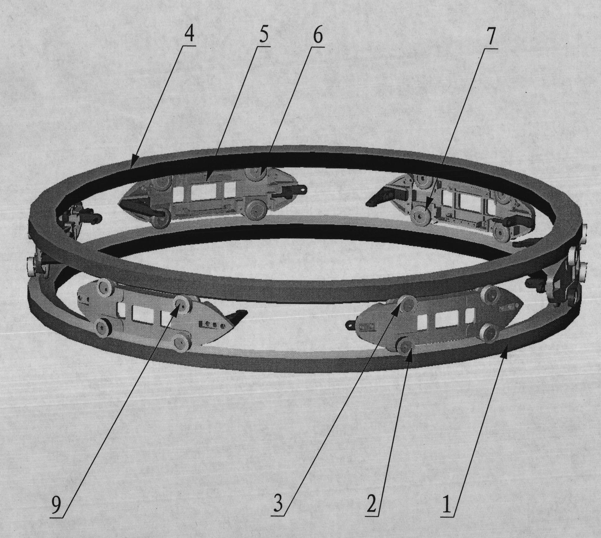
[0017] refer to figure 1 , figure 1 It is a structural schematic diagram of the first embodiment of the present invention, 1-lower door ring, 2-outside lower shuttle wheel, 3-outside upper shuttle wheel, 4-upper door ring, 5-shuttle hull, 6-inboard upper shuttle wheel, 7-Inside lower shuttle wheel, a shuttle boat and running track structure of a plastic circular loom, characterized in that the lower edge of the upper door ring 4 is designed as a double-cone surface, and the upper edge of the lower door ring 1 is designed as a double-cone surface , the inner cone surface of the upper door ring 4 and the inner cone surface of the lower door ring 1 form a set of shuttle wheel running tracks in the shape of an inner figure-of-eight, and the outer cone surface of the upper door ring 4 and the outer cone surface of the lower door ring 1 form an outer figure-of-eight shape. The running t...


PUM


Abstract

The invention relates to the field of plastic machinery, in particular to a shuttle ship and running orbit structure of a plastic circular weaving machine, which comprises a lower door ring, an outer lower shuttle wheel, an outer upper shuttle wheel, an upper door ring, a shuttle ship body, an inner upper shuttle wheel and an inner lower shuttle wheel and is characterized in that the lower edge of the upper door ring is designed into a double conical surface, the upper edge of the lower door ring is designed into a double conical surface, the shuttle ship is installed between the upper door ring and the lower door ring, and 6 to 8 shuttle wheels are installed on the shuttle ship, distributed at both sides of the shuttle ship body and distributed in two layers, wherein 4 shuttle wheels are in rolling contact with a pigeon-toed shuttle wheel running orbit comprising the upper door ring and the lower door ring to bear the running centrifugal force of a whole shuttle, and the other 2 to 4 shuttle wheels are in rolling contact with a splayfooted shuttle wheel running orbit comprising the upper door ring and the lower door ring to prevent the occurrence of shuttle flying. The invention overcomes various defects existing in the shuttle ship and running orbit structure on a circular weaving machine used at present, has fewer running stability faults, low noise, fewer wearing parts, low expenses and electricity saving.

Description

technical field [0001] The invention relates to the field of plastic circular looms, in particular to a shuttle boat and a running track structure of the plastic circular loom. Background technique [0002] At present, there are four types of shuttle boats and running track structures that use plastic circular looms at home and abroad. One is to rely on 4 shuttle wheels on the shuttle boat to run on the tapered runway of the upper and lower door rings; The 4 shuttle wheels run on the flat stepped runway of the upper and lower door rings, and the anti-flying shuttle relies on the shuttle bottom plate to slide and rub on the gate track between the upper and lower door rings; The anti-flying shuttle runs on the flat stepped runway of the door ring, relying on the shuttle bottom plate to run on the roller track between the upper and lower door rings; the fourth type uses 4 shuttle wheels on the shuttle boat to run on the upper and lower door ring flat stepped runway The anti-fl...

Claims


Application Information

Patent Timeline
IPC IPC(8): D03D49/50D03D37/00
Inventor 黄美昌陈崇锡周传对
Owner 黄美昌
Learn More