Break-proof method of insulator chain fracture caused by wind blowing
A technology of hanging insulators and insulator strings, which is applied in the installation of electrical components and cables, overhead installation, etc., and can solve the problems of poor vibration damping effect and unsatisfactory effect
- Summary
- Abstract
- Description
- Claims
- Application Information
AI Technical Summary
Problems solved by technology
Method used
Image
Examples
Embodiment 1
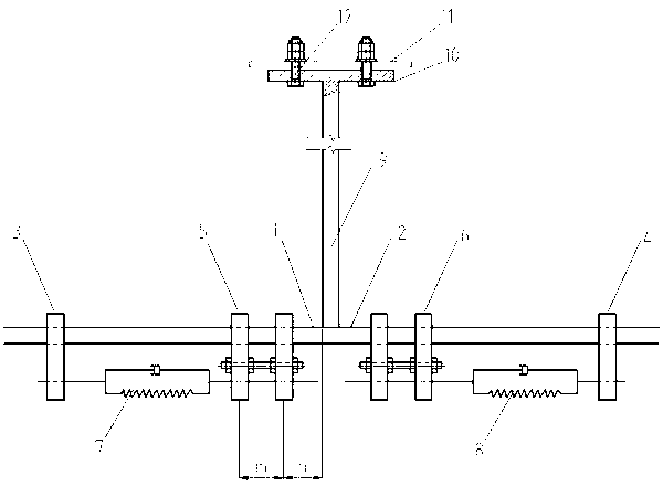
[0028] figure 1 It is a structural schematic diagram of Embodiment 1 of the wind-induced fracture prevention device for insulator strings of the present invention.
[0029] Such as figure 1 As shown, fixing fittings 5 and 6 are installed and fixed on the conductors 1 and 2 at a distance of 500 mm on the left and right sides of the suspension insulator string respectively. The fixing fittings are composed of two special fittings separated by 200 mm. The fittings are 1.5m wires, dampers 7 and 8 are arranged between the fixing fittings and the force transmission fittings; the fittings at the end of the insulator string 9 are provided with a "T"-shaped end 10, and the "T"-shaped end 10 is opened for The bolt hole 12 that is connected with the iron tower cross arm 11.
[0030] attached Figure 4 It is a structural schematic diagram of the force transmission fitting of the present invention. The force transmission fittings 3, 4 are composed of two clips, and the two clips are ...
Embodiment 2
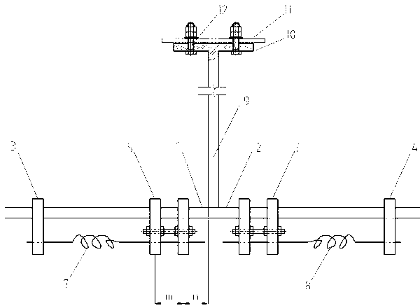
[0034] figure 2 It is a structural schematic diagram of Embodiment 2 of the wind-induced fracture prevention device for insulator strings of the present invention.
[0035] The fixing fittings 5 and 6 are respectively fixed on the wires 1 and 2 at a distance of 500 mm from the left and right sides of the hanging insulator string. The fixing fittings are composed of two special fittings separated by 200 mm. On the 1.2m wire, the fittings at the end of the insulator string 9 are provided with a "T"-shaped terminal 10, and the "T"-shaped terminal 10 is provided with a bolt hole 12 for connecting with the cross-arm 11 of the iron tower.
[0036] The dampers 7 and 8 are coil springs, disc springs or ring springs, as attached Figure 7 , 8 and 9.
[0037] The force transmission fittings 3 and 4, the fixing fittings 5 and 6 and the end structures of the insulator strings are the same as in the first embodiment.
Embodiment 3
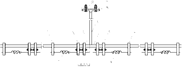
[0039] image 3 It is a structural schematic diagram of Embodiment 3 of the insulator string wind-induced fracture prevention device of the present invention.
[0040] Two pairs of damping systems consisting of force transmission fittings 3, 4, fixing fittings 5, 6 and dampers 7, 8 are respectively fixed on the conductors 1 and 2 on the left and right sides of the suspension insulator string, and the distance between the two pairs of damping systems is 2.5m.
[0041] The dampers 7 and 8 are coil springs, disc springs, ring springs or viscoelastic dampers.
[0042]The force transmission fittings 3 and 4, the fixing fittings 5 and 6 and the end structures of the insulator strings are the same as in the first embodiment.
[0043] The force transmission fittings 3, 4 and fixing fittings 5, 6 and the insulator string end fittings "T" shaped end 10 described in the above-mentioned embodiment one to example three can all be manufactured by general machining methods or casting meth...
PUM
 Abstract
Description
Claims
Application Information
 - R&D
- Intellectual Property
- Life Sciences
- Materials
- Tech Scout
- Unparalleled Data Quality
- Higher Quality Content
- 60% Fewer Hallucinations
Browse by: Latest US Patents, China's latest patents, Technical Efficacy Thesaurus, Application Domain, Technology Topic, Popular Technical Reports.
© 2025 PatSnap. All rights reserved.Legal|Privacy policy|Modern Slavery Act Transparency Statement|Sitemap|About US| Contact US: help@patsnap.com


