Structure for preventing flashover of power transmission circuit caused by windage yaw
A flashover structure and transmission line technology, which is applied in the field of preventing wind deflection flashover of transmission lines, preventing wind deflection flashover of insulator strings suspended by linear towers, and can solve the problem of increasing the vertical load of insulator strings and unsatisfactory actual effects, etc. It can achieve the effect of good windproof effect, suppress horizontal and torsional vibration, and reduce torque.
- Summary
- Abstract
- Description
- Claims
- Application Information
AI Technical Summary
Problems solved by technology
Method used
Image
Examples
Embodiment 1
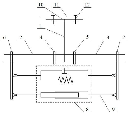
[0032] figure 1 It is a structural schematic diagram of Embodiment 1 of the method for preventing wind deflection flashover of transmission lines according to the present invention.
[0033] Such as figure 1 As shown, damping spacers 4, 5 are installed and fixed on the conductors 2 and 3 at a distance of 500 mm from the left and right sides of the suspension insulator string 1, and the left and right clamps 6 and 7 are respectively installed on the left and right conductors 2.0 m away from the suspension insulator string. Above, a damping system is provided between or on both sides of the wires of the suspension insulator string, that is, a damper system 8 is provided between the left and right wire clamps, and the damping system and the left and right wire clamps are hinged through a pull rod 9 Connection: The fitting at the end of the suspension insulator string 1 is provided with a "T"-shaped end 10, and the "T"-shaped end 10 is provided with a bolt hole 12 for connecting ...
Embodiment 2
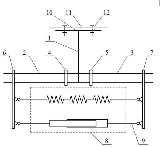
[0038] figure 2 It is a structural schematic diagram of Embodiment 2 of the method for preventing wind deflection flashover of transmission lines in the present invention.
[0039] The non-damping spacer bars 4 and 5 are respectively fixed on the conductors 2 and 3 with a distance of 800mm between the left and right sides of the suspension insulator string 1, and the left and right wire clamps 6 and 7 are respectively installed on the left and right conductors 2 and 3 at a distance of 2.5m from the suspension insulator string 1. 3. The damping system 8 is hinged to the left and right clamps 5 and 6 through the pull rod 9. The fittings at the end of the insulator string 9 are provided with a "T"-shaped end 10, and the "T"-shaped end 10 is opened for connection with the iron tower cross arm 11. 12 bolt holes.
[0040] The damping system is a composite damping system composed of three spring dampers in series and parallel with air dampers, as shown in the attached Figure 7 sh...
Embodiment 3
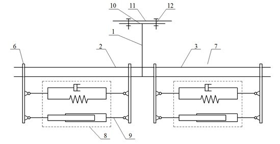
[0043] image 3 It is a structural schematic diagram of Embodiment 3 of the method for preventing transmission line wind deflection flashover according to the present invention.
[0044] On the conductors 1 and 2 on the left and right sides of the suspension insulator string 1, fix two pairs of damping systems consisting of clamps 5 and 6 and a damping system 8 respectively, and the distance between the two pairs of damping systems is 2.5m.
[0045]The damping system is a viscoelastic damper, an air damper or a spring damper, e.g. Figure 8-Figure 10 , or a composite damping system composed of them juxtaposed.
[0046] The structures of the clamps 5, 6 and the ends of the insulator strings are the same as in the first embodiment.
[0047] The spacer bars 4, 5, clamps 6, 7 and insulator string end fittings "T" shaped end 10 described in the first to third embodiments above can be manufactured by general machining or casting methods, and various dampers It can also be manufac...
PUM
 Abstract
Description
Claims
Application Information
 - R&D
- Intellectual Property
- Life Sciences
- Materials
- Tech Scout
- Unparalleled Data Quality
- Higher Quality Content
- 60% Fewer Hallucinations
Browse by: Latest US Patents, China's latest patents, Technical Efficacy Thesaurus, Application Domain, Technology Topic, Popular Technical Reports.
© 2025 PatSnap. All rights reserved.Legal|Privacy policy|Modern Slavery Act Transparency Statement|Sitemap|About US| Contact US: help@patsnap.com


