Structure for preventing flashover of power transmission circuit by windage yaw
A technology of flashover structure and transmission line, applied in the direction of mechanical vibration damping device, etc., can solve the problems of increasing the vertical load of the insulator string, the actual effect is not ideal, etc., achieving good windproof effect, suppressing horizontal and torsional vibration, reducing wind off-trend effect
- Summary
- Abstract
- Description
- Claims
- Application Information
AI Technical Summary
Problems solved by technology
Method used
Image
Examples
Embodiment 1
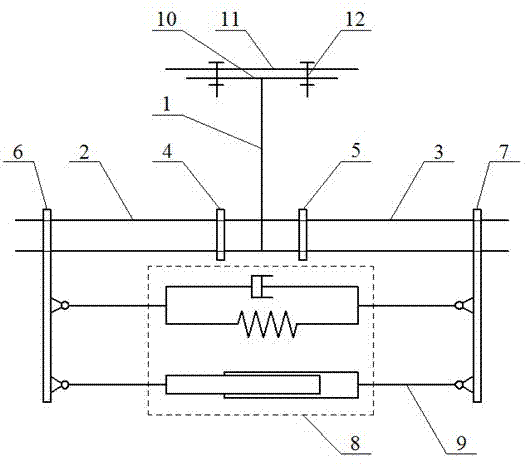
[0032] figure 1 It is a schematic structural diagram of Embodiment 1 of a method for preventing wind-deviation flashover of a transmission line according to the present invention.
[0033] Such as figure 1 As shown, damping spacers 4 and 5 are installed and fixed on the wires 2 and 3 with a distance of 500mm on the left and right sides of the suspension insulator string 1, and the left and right clamps 6, 7 are respectively installed on the left and right wires 2.0m away from the suspension insulator string. Above, there is a damping system between the wires on both sides of the suspension insulator string, or on the wires on both sides, that is, a damper system 8 is provided between the left and right clamps, and the damping system is hinged with the left and right clamps through the tie rods 9 Connection; the end fittings of the suspension insulator string 1 are provided with a "T"-shaped end 10, and the "T"-shaped end 10 is provided with a bolt hole 12 for connecting with the c...
Embodiment 2
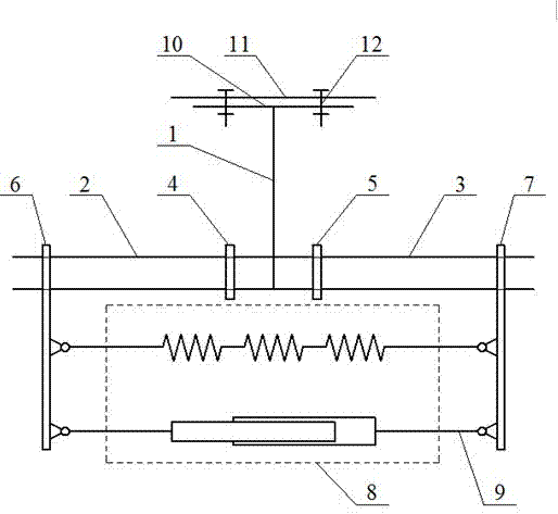
[0038] figure 2 It is a schematic structural diagram of the second embodiment of the method for preventing wind-deviation flashover of a transmission line according to the present invention.
[0039] The non-damping spacers 4 and 5 are respectively fixed on the wires 2 and 3 with a distance of 800mm between the left and right sides of the suspension insulator string 1, and the left and right clamps 6, 7 are respectively installed on the left and right wires 2 with a distance of 2.5m from the suspension insulator string 1. 3. The damping system 8 is hinged to the left and right clamps 5 and 6 through the tie rod 9. The end fittings of the insulator string 9 are provided with a "T" shaped end 10, and the "T" shaped end 10 is used to connect with the iron tower cross arm 11 的bolt hole 12.
[0040] The damping system is a composite damping system composed of 3 spring dampers in series and parallel with the air damper, as attached Figure 7 Shown.
[0041] The structure of the left and r...
Embodiment 3
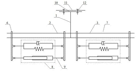
[0043] image 3 It is a schematic structural diagram of Embodiment 3 of the method for preventing wind-deviation flashover of a transmission line according to the present invention.
[0044] On the wires 1 and 2 on the left and right sides of the suspension insulator string 1, two pairs of damping systems composed of clamps 5, 6 and a damping system 8 are respectively fixed, and the two pairs of damping systems are separated by 2.5 m.
[0045] The damping system is a viscoelastic damper, air damper or spring damper, such as Figure 8-10 , Or a composite damping system composed of them side by side.
[0046] The end structures of the clamps 5 and 6 and the insulator string are the same as in the first embodiment.
[0047] The spacers 4, 5, wire clamps 6, 7 and the "T"-shaped end 10 of the end fittings of the insulator string described in the first to third examples above can all be manufactured by general machining methods or casting methods. Various dampers It can also be manufacture...
PUM
 Abstract
Description
Claims
Application Information
 - R&D
- Intellectual Property
- Life Sciences
- Materials
- Tech Scout
- Unparalleled Data Quality
- Higher Quality Content
- 60% Fewer Hallucinations
Browse by: Latest US Patents, China's latest patents, Technical Efficacy Thesaurus, Application Domain, Technology Topic, Popular Technical Reports.
© 2025 PatSnap. All rights reserved.Legal|Privacy policy|Modern Slavery Act Transparency Statement|Sitemap|About US| Contact US: help@patsnap.com


