
Bidirectional forced vibration experimental apparatus for FISHFRAM buoy segment model under action of inclined uniform flow

A segmented model and forced vibration technology, applied in the field of marine engineering, can solve the problems of large scale effect, limited simulation, limited test equipment, etc., and achieve the effect of avoiding scale effect and solving boundary effect.

Active Publication Date: 2012-01-11
SHANGHAI JIAO TONG UNIV
View PDF5 Cites 2 Cited by
  • Summary
  • Abstract
  • Description
  • Claims
  • Application Information

AI Technical Summary

Problems solved by technology

[0004] The purpose of the embodiment of the present invention is to provide a FISHFARM buoy segmented model dual-degree-of-freedom forced vibration experimental device under the action of oblique uniform flow, aiming to solve the problem that the existing test device is limited to the overall model, the scale effect is large, and it can only simulate In low KC number sea conditions, there is no boundary treatment for buoys, and it is limited to the simulation of downstream single-degree-of-freedom vibration, which cannot simulate the actual sea conditions more realistically

Method used


Image

  • Bidirectional forced vibration experimental apparatus for FISHFRAM buoy segment model under action of inclined uniform flow
  • Bidirectional forced vibration experimental apparatus for FISHFRAM buoy segment model under action of inclined uniform flow
  • Bidirectional forced vibration experimental apparatus for FISHFRAM buoy segment model under action of inclined uniform flow

Examples


Embodiment 1

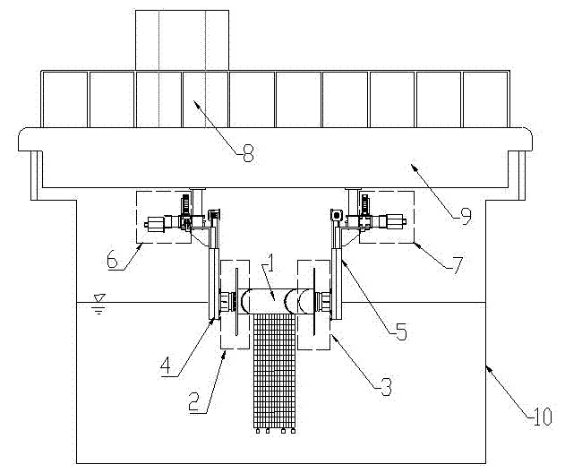
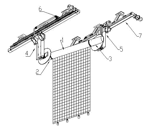
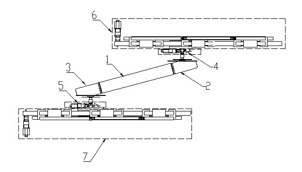
[0026]Such as figure 1 , figure 2 and image 3 As shown, the experimental device provided by the present invention includes: a buoy module 1, a first end prosthesis module 2, a second end prosthesis module 3, a first vertical sliding module 4, a second vertical sliding module 5, a second vertical sliding module A horizontal sliding module 6, a second horizontal sliding module 7 and a measurement analysis control module 8, wherein: the two ends of the buoy module 1 are respectively connected with the first end prosthesis module 2 and the second end prosthesis module 3, and the first vertical The sliding module 4 is respectively connected with the first end prosthesis module 2 and the first horizontal sliding module 6, and the second vertical sliding module 5 is respectively connected with the second end prosthesis module 3 and the second horizontal sliding module 7, and the first horizontal The sliding module 6 is fixedly connected to the bottom of one end of the trailer 9 a...


PUM


Abstract

The invention provides a bidirectional forced vibration experimental apparatus for a FISHFRAM buoy segment model under the action of inclined uniform flow, which comprises a buoy segment module, prosthesis modules, horizontal sliding modules, vertical sliding modules and a measurement analysis control module. Both ends of the buoy segment module are respectively connected with the end part prosthesis modules. The vertical sliding modules are respectively connected with the corresponding end part prosthesis modules and the corresponding horizontal sliding modules. The horizontal sliding modules are fixedly connected with the bottom of a trailer. The measurement analysis control module is connected with the buoy segment module, the prosthesis modules, the horizontal sliding modules and the vertical sliding modules. In the invention, the forced vibration can be carried out in two directions; the local stress of a fishing net can be measured; by arranging component balances inside the buoy module, the overall stress of the fishing net can be measured; by arranging component balances outside the buoy module, the overall stress of the fishing net and the buoy module can be measured; due to the adoption of the special end part prosthesis module devices, the problem of the boundary effect of the model is solved; and the test condition can reach an actual KC value range, the scale effect is avoided, and a certain included angle can be formed between the bidirectional forced vibration experimental apparatus and incoming flow so as to effectively simulate the special working condition.

Description

technical field [0001] The invention belongs to the field of marine engineering, and in particular relates to a bidirectional forced vibration experiment device of a FISHFARM buoy section model under oblique uniform flow. Background technique [0002] The entire FISHFARM structure is placed in the sea, and its upper buoys and fishing nets will be subjected to the hydrodynamic effects of ocean currents and waves. Therefore, the dynamic analysis of the overall structure of FISHFARM becomes the key to whether it can be applied to engineering practice, and most of the methods used are model tests. [0003] However, most of the existing test models are the overall model of FISHFARM. In the limited space of the test pool, a large scale ratio needs to be adopted, resulting in too small KC number, which inevitably leads to scale effects. Therefore, in order to simplify the research problem, in the study of FISHFARM's hydrodynamic response, theoretical researchers began to focus on ...

Claims


Application Information

Patent Timeline
Patent Type & Authority Applications(China)
IPC IPC(8): G01M7/06
Inventor 付世晓胡克陈蓥李鲤张蒙蒙
Owner SHANGHAI JIAO TONG UNIV
Learn More