Flow guiding device of fluid container and fluid container with flow guiding device
A technology of a diversion device and a fluid container, applied in the direction of a discharge device, etc., can solve the problems of liquid leakage, complicated production process, inconvenient use, etc.
- Summary
- Abstract
- Description
- Claims
- Application Information
AI Technical Summary
Problems solved by technology
Method used
Image
Examples
Embodiment 1
[0049] Embodiment 1 (fluid container diversion device)
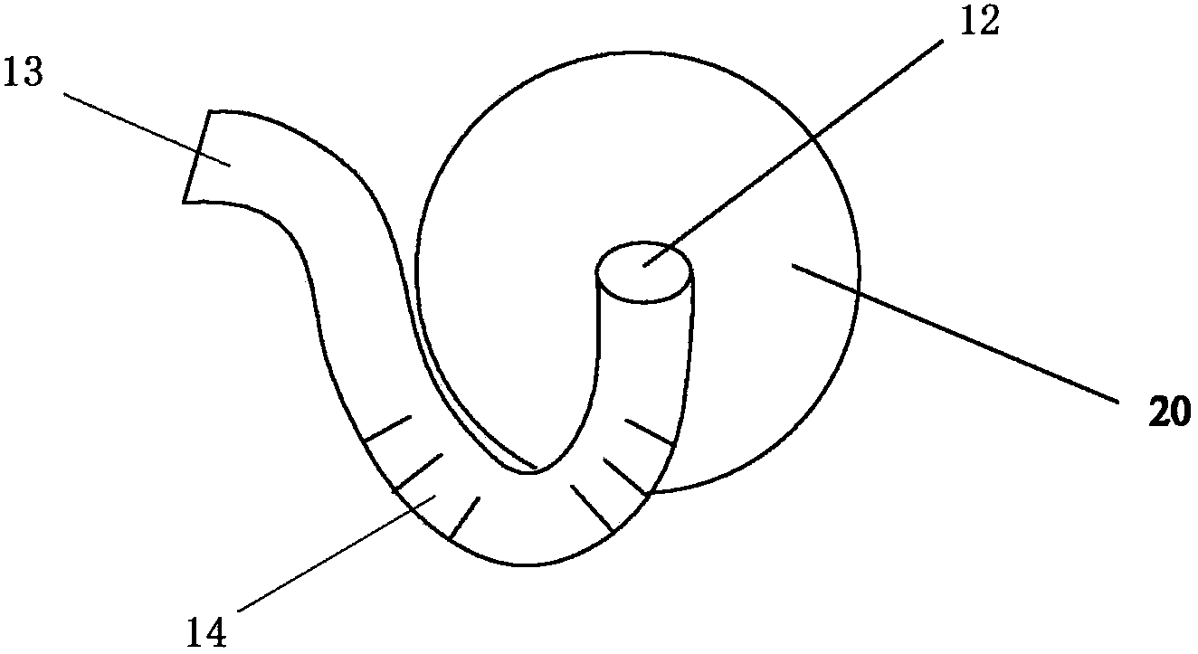
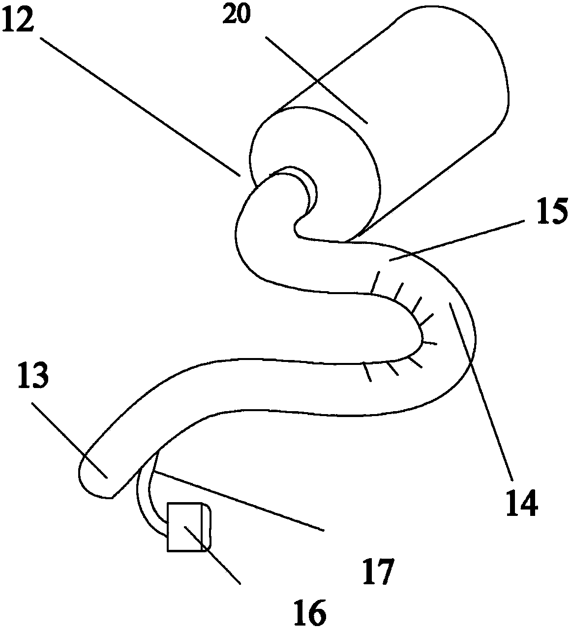
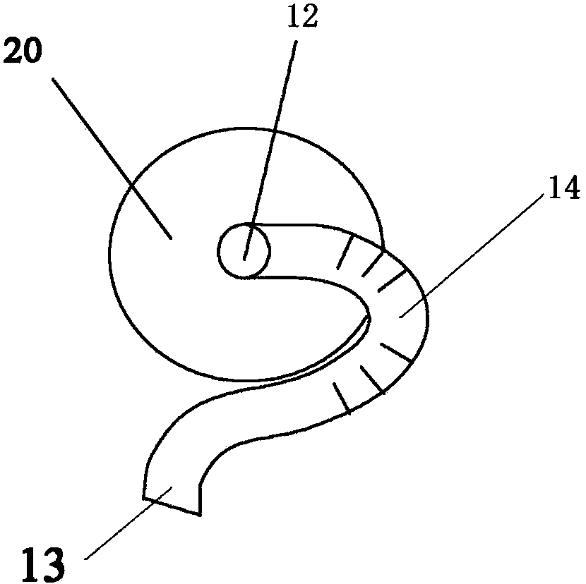
[0050] As shown in Figures 2 and 3, the fluid container diversion device 10 of the present invention is connected to the fluid container 20 at its diversion inlet 12, the fluid container 20 can be a common bottle, and the diversion device 10 is connected at its diversion outlet. 13 places can be externally connected to the fluid receiving container.
[0051] The main body 11 of the flow guiding device 10 is a pipe section made of transparent material with a U-shaped bending part. The "U"-shaped bending part is a spatially twisted U-shape, so the flow channels formed by it are not in the same plane. The diversion body 11 and the diverted fluid container 20 can independently store fluid at the same time. The connection between the body and the fluid container can also be regarded as the connection in the shape of "╮" in the initial state, and the connection in the shape of "╭" in the dumping state.
[0052] The lumen o...
Embodiment 2
[0057] Embodiment 2 (fluid container diversion device)
[0058] like figure 1 , Figure 5A , Figure 5B and Image 6 As shown, the difference from the above-mentioned embodiment 1 is that the pipe section of the diversion device 10 has a diversion inlet 12, a curved part (temporary storage part 14) and a diversion outlet 13 in the form of a "∝" shape in which the space is staggered. , and connected to the fluid container 20. In this embodiment, the fluid is as close as possible to the diverted container during the diversion process, and the torque is relatively reasonable when the diverted container is operated by hand, which is relatively labor-saving.
[0059] Under the condition that the fluid medium in the container 20 no longer flows out of the diversion outlet 13 from the temporary storage part 14 , the container 20 can be rotated so that the diversion flow 12 is gradually lower than the fluid medium volume level in the temporary storage part 14 .
[0060] Prefera...
Embodiment 3
[0066] Embodiment 3 (fluid container with deflector)
[0067] see Figure 8 As shown, the diverted container 30 of the present invention can be a cup body or a jug body, and a diversion device (the diversion device of embodiment 1 or 2, which can also be arranged on the inside or outer wall of the container) is arranged next to the container, and the diversion device can be connected with the diversion device The vicinity of the device body is a centripetal arc or a curved surface, the diversion inlet 31 is formed on the side wall of the cup body or the pot body, the diversion outlet 32 can be separated or not, and there is a certain distance between the outlet and the inlet; The tube section of the flow device body can be attached to the outer wall of the fluid container 30 and can be integrally formed with the outer wall of the fluid-guided container 30 . A U-shaped temporary storage part 33 is arranged in the inner cavity of the container. The embodiment of the cup or...
PUM
 Abstract
Description
Claims
Application Information
 - R&D
- Intellectual Property
- Life Sciences
- Materials
- Tech Scout
- Unparalleled Data Quality
- Higher Quality Content
- 60% Fewer Hallucinations
Browse by: Latest US Patents, China's latest patents, Technical Efficacy Thesaurus, Application Domain, Technology Topic, Popular Technical Reports.
© 2025 PatSnap. All rights reserved.Legal|Privacy policy|Modern Slavery Act Transparency Statement|Sitemap|About US| Contact US: help@patsnap.com


